Can someone please explain how an input signal and a bias voltage can be feed to the gate of a Mosfet without disturbing the input signal?
Taking from the original Zen as an example, page 3 states the following:
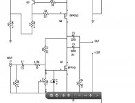
This constant 2 amp current is fed to Q1. Resistor R8 and potentiometer
P1 form a DC feedback loop which operates the gate of Q1 at about 4
volts and places the Drain potential of Q2 at the midway point of the
power supply, or about 17 volts. Input signal passes through C6 and R5
to the gate of Q1, and output signal passes through C3 and C4 in
parallel to the loudspeaker. R9 and R2 are there to bleed off DC, but are
not particularly essential. Z1 is essential to insure that an input transient
cannot exceed the 20 V gate rating of the Mosfet.
The 4 volt bias is needed to turn on the Mosfet. If there is a 1v audio signal at the input, do the voltages not interact or crash or mess each other up?
In the case of the Zen, DC bias is placed at the gate because of the type of amp- a common Source V+I gain?
This is one of those audio amp building mysteries I'm trying to understand.
Thanks in advance,
Vince
Taking from the original Zen as an example, page 3 states the following:
This constant 2 amp current is fed to Q1. Resistor R8 and potentiometer
P1 form a DC feedback loop which operates the gate of Q1 at about 4
volts and places the Drain potential of Q2 at the midway point of the
power supply, or about 17 volts. Input signal passes through C6 and R5
to the gate of Q1, and output signal passes through C3 and C4 in
parallel to the loudspeaker. R9 and R2 are there to bleed off DC, but are
not particularly essential. Z1 is essential to insure that an input transient
cannot exceed the 20 V gate rating of the Mosfet.
The 4 volt bias is needed to turn on the Mosfet. If there is a 1v audio signal at the input, do the voltages not interact or crash or mess each other up?
In the case of the Zen, DC bias is placed at the gate because of the type of amp- a common Source V+I gain?
This is one of those audio amp building mysteries I'm trying to understand.
Thanks in advance,
Vince
Attachments
you have cap there - between DC bias voltage and input AC voltage
just think of DC bias voltage/potential as AC GND
so - input signal is riding around DC bias potential without disturbing it
in most amps/stages GND is just state of mind , nothing else ...
"real" GND is "just" overall reference potential
just think of DC bias voltage/potential as AC GND
so - input signal is riding around DC bias potential without disturbing it
in most amps/stages GND is just state of mind , nothing else ...
"real" GND is "just" overall reference potential
just think of DC bias voltage/potential as AC GND
so - input signal is riding around DC bias potential without disturbing it
I though it was something like this, but I removed it from my post, because I was speculating. I need to better understand the relationship between AC and DC in audio signals?
Thanks ZM.
Vince
DC is 0 hertz, AC is x Hz. They don't interfere with each other. However, the way I understand it, when amplification happens, the input V at some frequency is impressed upon a much larger V which is at DC. What remains is the much larger V, but now it is transformed into an AC V.
What remains is the much larger V, but now it is transformed into an AC V
Is that varying DC?
Yup... exactly what ZM said. Output node can be the drain of the FET. When the FET receives an AC signal at the gate, the signal modulates or impresses itself on the 0 Hz (flat) signal at the drain of the FET. But because the drain is at much higher potential, you get gain or an amplified signal.
I'm sure its much more complex than that, but I find this way easier to understand.
I'm sure its much more complex than that, but I find this way easier to understand.
minor error but may cause confusion.Think of it as an AC signal riding on a DC level. For example, if the input DC bias voltage is 10 volts , and the AC input signal is 1 volt peak to peak, the resulting voltage at the amp input will be from 9 volts to 11 volts.
10Vdc and 1Vpp of AC signal = 9.5V to 10.5V of varying signal.
The -ve part of the AC waveform subtracts from the +ve DC flat voltage line. The +ve part of the AC waveform adds to the +ve DC flat voltage line.
")
- Status
- This old topic is closed. If you want to reopen this topic, contact a moderator using the "Report Post" button.
- Home
- Amplifiers
- Pass Labs
- Input signal and amp bias