Thanks for the schematics!
But in your schematic roy you have to maintain the input of the 4028 at the hi level for all the time, is it right? in this case you have to push the botton to select an input and to press it again to be able to choose another one...
@diy_audio_fo :my email is msabbatini@tiscali.it
But in your schematic roy you have to maintain the input of the 4028 at the hi level for all the time, is it right? in this case you have to push the botton to select an input and to press it again to be able to choose another one...
@diy_audio_fo :my email is msabbatini@tiscali.it
Hi simone,
I don't know exactly how it works I will have to look it up. But it works fine I use its myself and you don't have to push buttons twice just push anotherone and it will switch its cheap to build to the to IC's together will cost you about 2 or 3 euros.
greetings roy
I don't know exactly how it works I will have to look it up. But it works fine I use its myself and you don't have to push buttons twice just push anotherone and it will switch its cheap to build to the to IC's together will cost you about 2 or 3 euros.
greetings roy
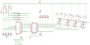
I looked at Roy's schematic and i think i have understant how the circuit works;
pushing the button we set one of the input of the BCD converter to an hi level and after the propagation time of the cd4028 whe have this hi level at one of the output...when we release the button the input level decreased and the diode (that was off) turns on and maintains the input to the hi level.
When we press another button all the output used of the cd4028 goes to the low level for a short time and then the selected output goes to the hi level and rest to this level due to the feedback introduced by the diode...
Is it right?
Thanks
Simone
- Status
- This old topic is closed. If you want to reopen this topic, contact a moderator using the "Report Post" button.