
Its called a 'ground lift resistor' and its not in series with the input signal. Its there to provide a relatively high resistance path to safety earth in an attempt to avoid current loops being set up between amp and source equipment.
Its highly questionable from an electrical safety point of view though as it'll easily fuse (go O/C) leaving an ungrounded touchable metal part (the RCA input socket) on the amp.
Its highly questionable from an electrical safety point of view though as it'll easily fuse (go O/C) leaving an ungrounded touchable metal part (the RCA input socket) on the amp.
think of your amplifier as a 5 pin opamp.
This simplified opamp/amplifier has the two differential inputs, two power pins and one output pin.
This opamp has no idea where to place the output voltage.
The Builder needs to add a voltage reference so that the opamp knows where to set the output voltage.
You add this reference by providing a voltage reference link from input return to speaker return.
But where is speaker return? It is connected to the common point between the power pins, the power ground.
So one connects the speaker return to the power ground and then the voltage reference from signal input gets connected to the same point where speaker return connects.
In a mono-block amplifier that is all that is needed.
But when multi-channel amplifiers are assembled there is a loop in the input circuits that picks up interference.
The way to attenuate this multi-channel interference is described by D.Joffe and his solution is to add HBRR & HBRL.
This is the 10r you refer to.
Last edited:
Its called a 'ground lift resistor' and its not in series with the input signal. Its there to provide a relatively high resistance path to safety earth in an attempt to avoid current loops being set up between amp and source equipment.
It provides enough resistance to break up unwanted ground loops. It is also a low enough resistance that the metal case will still provide Farady shielding.
Its highly questionable from an electrical safety point of view though as it'll easily fuse (go O/C) leaving an ungrounded touchable metal part (the RCA input socket) on the amp.
Yes, it presents a potential safety hazard and will not provide protection as shown in a worse case meltdown. It should be paralleled with a pair of back to back diodes large enough to withstand the maximum fault current available from the mains fuse. "Worst case" is the transformer isolation breaking down.
Without a mains fuse, it's not safe at all.
It should be noted that the use of this resistor allows you to use a three wire (grounded) power chord without introducing unwanted signal ground loops. And for our build it at home projects, I think a grounded mains connection is mandatory for safety.
DCblock.gif gif by dkleitsch | Photobucket
Resistor, cap, and a bridge (after Bryston).
Also shows DC blocker after Bryston, Crown.
Resistor, cap, and a bridge (after Bryston).
Also shows DC blocker after Bryston, Crown.
?????
The output signal voltage is the input signal voltage multiplied by a number defined by the feedback network.The Builder needs to add a voltage reference so that the opamp knows where to set the output voltage.
You add this reference by providing a voltage reference link from input return to speaker return.
In an unbalanced configuration, these voltages are all referenced to a theoretical potential of 0V called ground.
This 0V potential can't be anyting else than the one given by the signal at the input.
The get equipotentiality between the ground points of the input, the feedback network and the output, the impedance between them has to be the lowest as possible, with the least parasitic current circulating between them.
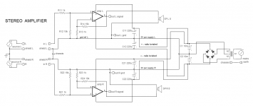
Not necessarily. Here a possible implementation. A very short path between the "grounds" of the input socket, R12, R13 (R22, R23) and out gnd is recommended. A local decoupling on the PCB cards is provided by C11, C12 and C21, C22.But where is speaker return? It is connected to the common point between the power pins, the power ground.
Attachments
I don't understand why you have said "not necessarily"................
Not necessarily. Here a possible implementation. A very short path between the "grounds" of the input socket, R12, R13 (R22, R23) and out gnd is recommended. A local decoupling on the PCB cards is provided by C11, C12 and C21, C22.
Looking at your example supposed to show something different, it looks to me exactly as I described.
The local decoupling meet and there the Speaker return joins up. That reference point is linked to the Signal return via a link you have labelled "gnd ref L".
Last edited:
But where is speaker return? It is connected to the common point between the power pins, the power ground.
I don't understand why you have said "not necessarily" Looking at your example supposed to show something different, it looks to me exactly as I described.
In the schematics of my previous post, the speaker is connected slightly ahead of the midpoint of the local power supply decoupling caps. That's the difference.
I wonder if there is any benefit brought by the inclusion like in post #1 schematics of a 10 Ohm resistor in the input and feedback ground connections.
I am even not sure that it has no deleterious effects at all. My amps have never needed such a configuration to be free of any trace of hum.
There is no difference.
remove the link labelled "gnd ref L"
Now the signal return side is still connected up to form the input circuits.
The power side is still connected up to form the output circuits. Particularly the speaker current flows from the out pin to the load back to the decoupling ground and then returns to the source.
Now add back in the voltage reference link. You are back to your scheme.
It is exactly the same.
The two sides, input and output, are completed to allow all the currents to return to their sources.
Add the voltage reference link.
You did not provide a schematics to show your conception of a good grounding technique. I did. The point in the layout on which I insiste is that is the equipotentiality between the "grounds" the input socket, R12, R13 and the out gnd (for the left channel). It is obtained by a path of very short length and of very low impedance between them, without current circulating in it. This obviates using the 10 Ohm of post #1.There is no difference.
remove the link labelled "gnd ref L"
Now the signal return side is still connected up to form the input circuits.
The power side is still connected up to form the output circuits. Particularly the speaker current flows from the out pin to the load back to the decoupling ground and then returns to the source.
Now add back in the voltage reference link. You are back to your scheme.
It is exactly the same.
The two sides, input and output, are completed to allow all the currents to return to their sources.
Add the voltage reference link.
D.Joffe's article on the external loop created by attaching a multi-channel amplifier to a multi-channel Source where the source combines the returns needs HBRR & HBRL to attenuate the interference currents.
The only way I know to avoid that added interference is to build a mono-block receiver. The mono-block very effectively avoids the loop and thus avoids the added interference.
The only way I know to avoid that added interference is to build a mono-block receiver. The mono-block very effectively avoids the loop and thus avoids the added interference.
Most systems with multiways loudspeakers are based on stereo amps (mine for example 3 * stéreo amps). Without any special care, they do not suffer from interferences. Why ?D.Joffe's article on the external loop created by attaching a multi-channel amplifier to a multi-channel Source where the source combines the returns needs HBRR & HBRL to attenuate the interference currents.
The only way I know to avoid that added interference is to build a mono-block receiver. The mono-block very effectively avoids the loop and thus avoids the added interference.
Concentrate on where and how the interferences attack instead on the presence of loops.
What is you kind of connections ? unbalanced, balanced, RCA, XLR ?i see the use/need for the 10R decoupling resistor being dependant on other factors.
setup 1 - 1 foot of wiring from preamp to PA with a low gain PA = no noise
setup 2 - 14 feet of wiring from preamp to PA with a higher gain PA = noise
Are you saying you have an alternative method to D.Joffe for attenuating the interference current in the input leads of a stereo amplifier?.............Concentrate on where and how the interferences attack instead on the presence of loops...............
If so, could you please show us/me.
What is you kind of connections ? unbalanced, balanced, RCA, XLR ?
as per the OP and figure in post 1, I refer to unbalanced systems.
A stereo unbalanced connection is made of two shielded cables wires, with the same ground at both ends. Precaution #1 is to keep them parallel as much as possible such that they follow the same path. Many hum problems have been cured by this simple way.as per the OP and figure in post 1, I refer to unbalanced systems.
I do not remember D. Joffe's method (I have the paper), mine is the one in the schematics I already showed, I must add that all the paths are very short bar, sometimes, the connection to the power supply. As it has been successful since some years, I don't think I need an other method. However, due to respect to D. Joffe, I will have a look at his method again.Are you saying you have an alternative method to D.Joffe for attenuating the interference current in the input leads of a stereo amplifier? If so, could you please show us/me.
Last edited:
The output signal voltage is the input signal voltage multiplied by a number defined by the feedback network.
In an unbalanced configuration, these voltages are all referenced to a theoretical potential of 0V called ground.
This 0V potential can't be anyting else than the one given by the signal at the input.
The get equipotentiality between the ground points of the input, the feedback network and the output, the impedance between them has to be the lowest as possible, with the least parasitic current circulating between them.
Not necessarily. Here a possible implementation. A very short path between the "grounds" of the input socket, R12, R13 (R22, R23) and out gnd is recommended. A local decoupling on the PCB cards is provided by C11, C12 and C21, C22.
You still have a potential loop around the internal ground between where you strap the input sockets GND to the chassis and the connection back to the PCB although I think this may be lower than if you took the input grounds back to the PCB without the strap. You could of course use the HBR resistors in your config and possibly get even lower noise.
In all cases, the objective is to avoid getting noise that appears in series with the signal from the source by minimizing loop areas, providing alternative paths for ground loops to flow (i.e. Away from the interconnect) and attenuating loop currents using HBR techniques.
I am using the standard HBR approach and get better than -100 dB (independently verified) so it is a very powerful technique for the elimination ground loops in unbalanced systems.
- Status
- This old topic is closed. If you want to reopen this topic, contact a moderator using the "Report Post" button.
- Home
- Amplifiers
- Solid State
- Input Resistor