This is a description of input and switch boards for the Soekris DAM1021 DAC.
The Group Buy thread is here.
At this time all boards are sold out. Updated boards will be available after the release of the new DAM1021 firmware to enable convenient connectivity for new functions.
IMPORTANT! The previously shipped V1.1 boards contain an error that causes the 3.3V regulator on the input board to run excessively warm. It is strongly recommended to implement the fix described in ERRATA section below. Those who do not feel comfortable doing it themselves, can mail the board to me and I will do the modification and send the board back free of charge. All the boards shipped from now on will have the fix implemented
Here is the BOM: DAM input board V1.1 BOM (Google sheets)
Connectivity
Description
The physical dimensions allow to fit the DAM1021 DAC with the input board, TOSLINK, BNC COAX and Amanero USB interfaces attached into a 1U (40mm height) case with minimum internal depth of 220 mm.
All SMD resistors, capacitors and LEDs are 0805 size.
The SPDIF transformer pads have 10x5 mm footprint, fits Murata DA101C or Pulse Electronics PE-65612NL transformers.
The input board contains schottky diodes to allow use of a single pole switch for input selection.
The front panel board accepts Lorlin CK series switches, such as CK1051 or CK1061. Input selector and power LEDs can be soldered directly on the board, or 2.54mm pin headers can be mounted in place of LEDs to allow different LED placement. With the 330 ohm series resistors, the LED current is about 5-7mA, depending on the actual LED used.
The board is powered from DAM1021 J2 header. It uses PWR +1.2V line to reference the SPDIF differential input, and PWR A+ line as input to 3.3V regulator. The 3.3V regulator powers the TOSLINK receiver, front panel LEDs, and is used for volume pot 3.3V reference.
The entire DAM1021 J2 and J3 and Amanero headers have been duplicated, so ALL pins on those headers are accessible.
To fit everything into a 1U case, a right angle ribbon cable connector must be used for J5. If there are no height constraints, using a straight connector is more convenient.
These drawings are for boards assembled with ORJ-5 Toslink module and a low profile BNC connector. The dimensions may need to be adjusted if using different components.
Input board connector dimensions (PDF file)
Back panel openings for input connectors (PDF file)
Input board layout:

Front panel switch board layout:

Boards with SMD parts assembled:

Back side:

The alternative connection schematic shows how to connect the volume pot, the power led and a single pole input selector switch directly to the J5 "front panel" header on the input board.

Pricing
The boards are available only as a set.
One set of bare boards is 13 EUR.
A kit of SMD parts (resistors, capacitors, LEDs, voltage regulator IC and U.FL sockets) is 6 EUR. No other connectors or through hole components included.
A set of boards with preassembled SMD components (resistors, capacitors, LEDs, voltage regulator IC and three U.FL sockets for I2S) is 35 EUR. No other connectors or through hole components included. Pictures of assembled test boards are in post #98.
Shipping and handling 5 EUR by regular mail to anywhere in the world.
1 EUR for each set sold will be donated to diyAudio forum.
Payment by Paypal only.
ERRATA
Version 1.1 of the input boards contain an error which causes the 3.3V regulator to run very warm. It can also have an effect on the power supply of the DAM1021 DAC and therefore slightly impact the sound quality.
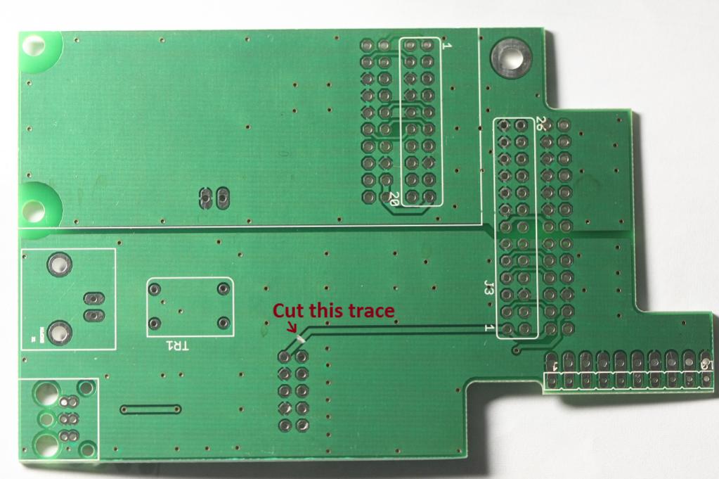
It is strongly recommended to implement this fix. On the back side of input board cut the trace connecting the "front panel" connector with the J3 connector as shown in the picture. There are no other traces nearby that could be damaged, but make sure neither end of the cut trace gets shorted to the surrounding ground plane. That is all that needs to be done.
Those who do not feel comfortable doing it themselves, can mail the board to me and I will do the modification and send the board back free of charge.
The Group Buy thread is here.
At this time all boards are sold out. Updated boards will be available after the release of the new DAM1021 firmware to enable convenient connectivity for new functions.
IMPORTANT! The previously shipped V1.1 boards contain an error that causes the 3.3V regulator on the input board to run excessively warm. It is strongly recommended to implement the fix described in ERRATA section below. Those who do not feel comfortable doing it themselves, can mail the board to me and I will do the modification and send the board back free of charge. All the boards shipped from now on will have the fix implemented
Here is the BOM: DAM input board V1.1 BOM (Google sheets)
Connectivity
- Directly connects to J3 and J2 headers on the DAC.
- Directly connects to header on Amanero USB/I2S adapter.
- Coaxial SPDIF input with BNC connector footprint.
- Optical TOSLINK input with footprints for Toshiba TORX147L and Cliff Electronics ORJ-5 receivers.
- U.FL sockets for other I2S sources (can be installed, but not used simultaneously with Amanero).
- Optional U.FL sockets for Amanero MCLK OUT, I2S MCLK OUT, FPGA SLV and FPGA MCLK OUT lines.
- Available connections to ALL pins on DAM1021 J2 and J3, and Amanero headers.
Description
The physical dimensions allow to fit the DAM1021 DAC with the input board, TOSLINK, BNC COAX and Amanero USB interfaces attached into a 1U (40mm height) case with minimum internal depth of 220 mm.
All SMD resistors, capacitors and LEDs are 0805 size.
The SPDIF transformer pads have 10x5 mm footprint, fits Murata DA101C or Pulse Electronics PE-65612NL transformers.
The input board contains schottky diodes to allow use of a single pole switch for input selection.
The front panel board accepts Lorlin CK series switches, such as CK1051 or CK1061. Input selector and power LEDs can be soldered directly on the board, or 2.54mm pin headers can be mounted in place of LEDs to allow different LED placement. With the 330 ohm series resistors, the LED current is about 5-7mA, depending on the actual LED used.
The board is powered from DAM1021 J2 header. It uses PWR +1.2V line to reference the SPDIF differential input, and PWR A+ line as input to 3.3V regulator. The 3.3V regulator powers the TOSLINK receiver, front panel LEDs, and is used for volume pot 3.3V reference.
The entire DAM1021 J2 and J3 and Amanero headers have been duplicated, so ALL pins on those headers are accessible.
To fit everything into a 1U case, a right angle ribbon cable connector must be used for J5. If there are no height constraints, using a straight connector is more convenient.
These drawings are for boards assembled with ORJ-5 Toslink module and a low profile BNC connector. The dimensions may need to be adjusted if using different components.
Input board connector dimensions (PDF file)
Back panel openings for input connectors (PDF file)
Input board layout:
Front panel switch board layout:
Boards with SMD parts assembled:
Back side:
The alternative connection schematic shows how to connect the volume pot, the power led and a single pole input selector switch directly to the J5 "front panel" header on the input board.
Pricing
The boards are available only as a set.
One set of bare boards is 13 EUR.
A kit of SMD parts (resistors, capacitors, LEDs, voltage regulator IC and U.FL sockets) is 6 EUR. No other connectors or through hole components included.
A set of boards with preassembled SMD components (resistors, capacitors, LEDs, voltage regulator IC and three U.FL sockets for I2S) is 35 EUR. No other connectors or through hole components included. Pictures of assembled test boards are in post #98.
Shipping and handling 5 EUR by regular mail to anywhere in the world.
1 EUR for each set sold will be donated to diyAudio forum.
Payment by Paypal only.
ERRATA
Version 1.1 of the input boards contain an error which causes the 3.3V regulator to run very warm. It can also have an effect on the power supply of the DAM1021 DAC and therefore slightly impact the sound quality.
It is strongly recommended to implement this fix. On the back side of input board cut the trace connecting the "front panel" connector with the J3 connector as shown in the picture. There are no other traces nearby that could be damaged, but make sure neither end of the cut trace gets shorted to the surrounding ground plane. That is all that needs to be done.
Those who do not feel comfortable doing it themselves, can mail the board to me and I will do the modification and send the board back free of charge.
Attachments
-
 IMG_8634.JPG197.3 KB · Views: 1,320
 -
 IMG_8635.JPG165 KB · Views: 1,272
 -
 dam1021-frontpanel-v1.1-brd.png26.7 KB · Views: 1,283
 -
 dam1021-input-board-v1.1-brd.png74.9 KB · Views: 1,308
 -
 dam1021-input-board-v1.1-sch.png59.1 KB · Views: 225
 -
 dam1021-frontpanel-v1.1-sch.png19.4 KB · Views: 186
 -
 dam1021-input-board-alt-conn-v1.1-sch.png9 KB · Views: 1,305
 -
Input board v1.1 drills.pdf15.3 KB · Views: 421
-
Input board v1.1 measures.pdf27 KB · Views: 366
-
 input_brd_correction.jpg75 KB · Views: 1,737