For a single DAM build, the RXD0/TXD0 lines are used. RXD1/TXD1 are connected to the second DAM in balanced build, when serial port chaining is not used. It would require special configuration on RPi side to define a second serial port on these pins.
RN3 is a 1k resistor array that limits current to RPi GPIO pins to protect them in case of GPIO misconfiguration. If it blocks the signal, there is a chance it may not be soldered properly. Check it with a loupe to see if all pins are actually soldered. You can also check pcb continuity. Disconnect Raspberry and DAM, and measure resistance between pin8 of J19 connector and pin14 of the 26-pin connector (which is basically a breakout of DAM J2), and between pin 10 of J19 and pin 16 of 26-pin connector. Each should be 1 kOhm.
Also check the resistance between pin8 and pin10 of J19. It should be open circuit.
Thanks for releasing the schematics, it helps... should save you some questions.
I checked the RX0/TX0 lines
- J3.pin14 (DAM RX) was not connected (not soldered on the big pad to CF3) to 26.pin14; I made a small bridge
- J3.pin16 (DAM TX) was not connected (not soldered on the big pad to CF4) to 26.pin16; I made a small bridge
- pin 4 of RN3 was not connected, but was not the main problem. I had my multimeter too often on RN3, so it got completely loose from the board, managed to resolder it somehow...
I have some serial response on the RPI now, the end is in sight....
The forta dam1021.py python script kinda works (I can set volumes...)
Thanks for the support.
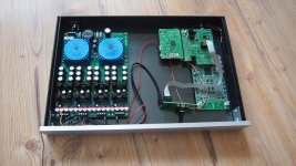
Here is my build with huge psu
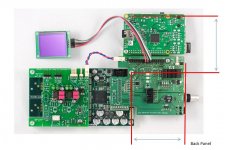
Is there anywhere a drawing with raspberry to make my back panel of the enclosure ?
I find some drawings, but not all need measurements.
Not at the moment.
Another forum member (who actually knows something about mechanical engineering) is working on it.
Thanks for releasing the schematics, it helps... should save you some questions.
I checked the RX0/TX0 lines
- J3.pin14 (DAM RX) was not connected (not soldered on the big pad to CF3) to 26.pin14; I made a small bridge
- J3.pin16 (DAM TX) was not connected (not soldered on the big pad to CF4) to 26.pin16; I made a small bridge
- pin 4 of RN3 was not connected, but was not the main problem. I had my multimeter too often on RN3, so it got completely loose from the board, managed to resolder it somehow...
I have some serial response on the RPI now, the end is in sight....
The forta dam1021.py python script kinda works (I can set volumes...)
Thanks for the support.
Sorry about the bad solder joints. I did catch and fix a couple of boards like that, but apparently something slipped by. If anyone else experiences strange behaviour with something not working, let me know by PM or here, and we will try to work out the problem.
Hello,
I have a v1.0 board and wants to power the Amanero with an external PS instead of the USB.
I've already corrected the error on +3.3v PS line on the PCB.
Are the following steps correct ?
- interrupt the USB +5vdc PS.
- add +3.3vdc to the Amanero duplicate headers
- something else needed ?
Regards,
Danny
Not at the moment.
Another forum member (who actually knows something about mechanical engineering) is working on it.
What a pity

Then i have to wait...
Do you have the two measurements in attached picture ?
In this case i can build my casing bottom .
Thanks
Attachments
Hello,
I have a v1.0 board and wants to power the Amanero with an external PS instead of the USB.
I've already corrected the error on +3.3v PS line on the PCB.
Are the following steps correct ?
- interrupt the USB +5vdc PS.
- add +3.3vdc to the Amanero duplicate headers
- something else needed ?
Regards,
Danny
That should work. Keep in mind that the same 3.3V supply will also be powering all the LEDs and the DAM isolators.
Do you have the two measurements in attached picture ?
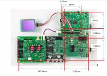
The distance from the DAM mounting hole to input board edge is 75.53 mm.
The distance from the DAM mounting hole to the LOWER mounting holes on RPi (that attach to the RPi connector PCB) is 29.21 mm. You should be able to find the to find the RPi dimensions on the Internet.
The distance from the DAM mounting hole to input board edge is 75.53 mm...
Thanks! You are great!

Do you mean 75.53 mm to the edge of the PCB or the edge from the toslink and bnc connectors?
I forgot one distance marked with ??? This distance is from mounting hole to the middle of Raspberry 40pin connector to get the distance to the mounting hole (left top) of the Raspberry.
http://www.raspberrypi-spy.co.uk/wp-content/uploads/2014/07/raspberry_pi_model_b_plus_dimentions.png
I hope you can call it.
That is to the edge of PCB. The Coax connector is protruding a bit beyond that, but the exact amount may vary somewhat depending on the connector model. If using standard M3 standoffs and mounting screws for the USB interface, they can also be protruding a bit. That was the main reason I moved the Coax connector outwards, so that the back panel fits against it.Do you mean 75.53 mm to the edge of the PCB or the edge from the toslink and bnc connectors?
I forgot one distance marked with ??? This distance is from mounting hole to the middle of Raspberry 40pin connector to get the distance to the mounting hole (left top) of the Raspberry.
http://www.raspberrypi-spy.co.uk/wp-content/uploads/2014/07/raspberry_pi_model_b_plus_dimentions.png
I hope you can call it.
That is 21.03 mm.
Documentation link
To people requesting access to outdated documentation versions that may be linked from various messages on this thread:
Please use the document link on the first page of this thread, since that is the only place I can update it !!! All other links are out of date.
To people requesting access to outdated documentation versions that may be linked from various messages on this thread:
Please use the document link on the first page of this thread, since that is the only place I can update it !!! All other links are out of date.
The distance from the DAM mounting hole to input board edge is 75.53 mm.
The distance from the DAM mounting hole to the LOWER mounting holes on RPi (that attach to the RPi connector PCB) is 29.21 mm. You should be able to find the to find the RPi dimensions on the Internet.
Hi,
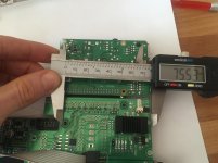
this distance is not correct (see attachement) . Please send me the correct distance.
Thanks
Attachments
Hi,
this distance is not correct (see attachement) . Please scend me the correct distance.
Thanks
You should measurements center-to-center or outer side to inner side of the holes not outer side to outer side, which it looks like you have done.


Hi normundss,
I am trying to trace an issue with the DAM losing lock. I have v1.1 input board but I am not using the front panel input board. Can I ask what the function of D1 is? I guess it is a back to back schottky diode? The cathodes of the back to back diodes are connected to an unused (by the front panel board) pin 6 on the input board connector J5?
I am trying to trace an issue with the DAM losing lock. I have v1.1 input board but I am not using the front panel input board. Can I ask what the function of D1 is? I guess it is a back to back schottky diode? The cathodes of the back to back diodes are connected to an unused (by the front panel board) pin 6 on the input board connector J5?
- Home
- Group Buys
- Input and switch boards for Soekris DAM1021 DAC