...
It is very well known around the PA people that most of INKEL and earlier Inter M amplifiers are notorious for shelf destroying or generally destroy any speaker connected on them ..
I dont really think that there is any operative MA 620 as we speak but just in case here is the info :
I have a MA620 since more that 15 years, a friend of mine bought two (for
biamping) at the same time, all three work like on the first day.
...
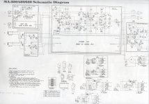
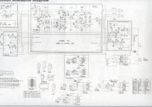
At the MA 620 the pcb designer skipped or failed to design a proper vbe multiplier attached on the heatsink...The related parts are located on the pcb ...combine this with the poor ""natural "" cooling, the only vent exists in the device will ventilate the inside of the amp while the transistors will dissipate heat only from the quite big heat sink .... that is thermal run away
I have mine biased 50mA per device (100mA total) and never experienced
thermal runaway. The heatsinks only get slightly warm (barely noticeable).
...
Now think ... the ventilator will cool down the inside of the amplifier... ...Double thermal run away .
There is no ventilator in the MA620.
...
Please replace Q109 R,L with a BD 139 use 3 leads of cable and attach firmly in any existing screws of middle output transistors .....
Might nevertheless be a good idea. Here I agree with you.
...
Adjust for 10mv over 0.27 ballast resistors
Expect the suggestion to preserve a very stable bias and start to decrease in a marginal level for distortion around 70 degrees on the heat sink but one way or another at this temperature the double safety thermostat will shut you
This is only 37mA and will bring you nowhere near 70 deg.
Last edited:
setting bias on a INKEL MA 320
Hi Guys, thanks for this post. I have just been looking at the 320. It had been over heating and shutting down from time to time. When i removed it from my friends bar i noticed that one side was hot so i was hoping that a bias adjustment might do the trick. One side (the cold one) was at around 3mv and the hot side was around 400mv. There is a lot of black from overheating. Following this thread i set the bias to 10mv per side. Is this ok for the 320?
I am thinking to do the mod on Q109 R&L mentioned here, if it really helps but now the amp appears cool and i am about to try audio through it. Seems like the output stage survived the bad bias settings, i am thinking to clean the pots with isopropyl as perhaps they are dusty or oxidised. I am also repairing a power supply on a yamaha amp and i found the bias pot was damaged, i noticed these are usually carbon but i have replaced it with a blue trimming pot, the type that can be turned many times (usually found on power supply voltage adjustment). Does anyone know if it is ok to use this type of potentiometer?
I also noticed that on this MA 320 the main smoothing caps are bulging on-top so i will recommend he replaces those soon.
Still trying to understand what bias does and how it works. What effects does bias have when you set it at a higher or lower mv?
Thanks.
James
James,
10mV is ok for these amps. This means a current of 40mA per power transistor and that will do. You can use the multi turn pots but be shure that they are in the max. resistant position when turned on. Or else your amp may blow up. Be carefull with these pots. The caps on the power capacitors may look bad but most of the time they are oke. The ESR (resistant) value will tell you if they are drying and dying. And ofcource the capacity.
The bias sends a current through the drivers and the power transistors. This is the part around Q109, the diodes etc. Bias makes the transistor a bit turned on. When the signal goes from positive to negative or vice versa the transistors stay on. If too low you get crossover distortion. This is a cracking sound. very ugly! If too high things get hot and your amp may blow up. Class A amps have a high bias current and a high bill from the energy company.... But may sound great! They are especially designed to operate in Class A.
I have two MA920 in the attic. Interested???
What does the other pot do?
I think i made a mistake when i said 400mv across the balast resistor, it was probably 40mv, after cleaning the pots i checked quickly to see how high the voltage drop could become and it was around 100mv max. They are set to 10mv each now and the pots are clean(er). But what does the other pot in the centre of the circuit do? Anyone?
CORRECTION
It is not a pot in the centre of the amp, there is one for each side more towards the left side of each amp circuit. But i still don't know what it is for. Is it the bias for a pre amp? Does anyone know how to set them?
Last edited:
James,
10mV is ok for these amps. This means a current of 40mA per power transistor and that will do. You can use the multi turn pots but be shure that they are in the max. resistant position when turned on. Or else your amp may blow up. Be carefull with these pots. The caps on the power capacitors may look bad but most of the time they are oke. The ESR (resistant) value will tell you if they are drying and dying. And ofcource the capacity.
The bias sends a current through the drivers and the power transistors. This is the part around Q109, the diodes etc. Bias makes the transistor a bit turned on. When the signal goes from positive to negative or vice versa the transistors stay on. If too low you get crossover distortion. This is a cracking sound. very ugly! If too high things get hot and your amp may blow up. Class A amps have a high bias current and a high bill from the energy company.... But may sound great! They are especially designed to operate in Class A.
I have two MA920 in the attic. Interested???
Great information here. Thanks for the explanation. I told the owner that he probably need not replace the smoothing caps. The tops are bulging but when i push on the plastic cover they just feel hollow beneath. There is no hum but they don't seem to store energy for long as when i removed the board to measure the pin/lead spacing i shorted them to be safe and just to see but there was no spark. I expect the amplifier had drained them. As when i turn off the amp whilst it is playing it continues to play for a few seconds. So they are probably fine. I was finding replacements to cost around €10 euros for 2 and i was quoting €20 to do the job. No need especially when it is just one of two amplifiers that play background music in a restaurant.
Regarding the 2x MA920's i am good for now thanks. I have so many amplifiers
 But i sometimes sell amps if a bar or restaurant needs something.
 Any ideas what the pot in the centre of the amp is there to adjust? Or how to set it?
As you have 2 of the MA920 amps perhaps you could bridge them and run them as a pair of mono's do you know what loads they are happy to drive? Would one drive an ESL57 ?
PS. I have just seen that the other pot was not one in the centre but there is one on each side of the amp SMVR R109 (R or L) towards the bottom left side of each amp circuit. Is this also to set bias? For a pre amp circuit perhaps? Any ideas how to set these up?
Last edited:
Inkel ma930 diode zener
good evening. i have a problem with amplifier, inkel ma930. the problem that audio is ok but led signals do not turn on. I disconnected amplifier, I checked input board, all electronic components. in input board be control for led -40 / -20db signal and led for -20 / -0db signal. the amplified signal comes in input board, is attenuated and filtered and enters the ne5532 integrated circuit and after being led for -40 and -20 db and then -20 to 0 db. the electronic components are all ok but I think a zener diode will be dead. this diode be in parallel with 180k ohm resistance and connected with pin 6 and pin 7 integrated circuit ne5532. the value of the diode is not visible and in service manual the value is not written. someone can tell me the value of this diode
good evening. i have a problem with amplifier, inkel ma930. the problem that audio is ok but led signals do not turn on. I disconnected amplifier, I checked input board, all electronic components. in input board be control for led -40 / -20db signal and led for -20 / -0db signal. the amplified signal comes in input board, is attenuated and filtered and enters the ne5532 integrated circuit and after being led for -40 and -20 db and then -20 to 0 db. the electronic components are all ok but I think a zener diode will be dead. this diode be in parallel with 180k ohm resistance and connected with pin 6 and pin 7 integrated circuit ne5532. the value of the diode is not visible and in service manual the value is not written. someone can tell me the value of this diode
Hello, please give me a copy of the service manual for INKEL MA-620 at mail andreimli85@gmail.com
- Status
- This old topic is closed. If you want to reopen this topic, contact a moderator using the "Report Post" button.
- Home
- Amplifiers
- Solid State
- Inkel MA-620 Schematic