Netlist said:Edwin,
Whether I short the inputs or not, the hum stays the same. Because it's 100Hz it comes from the PSU, so IMO it has nothing to do with grounds or inputs.
I'm getting more and more convinced that the CRCRC option could bring the solution. As I only have four caps of 68.000µF it will be CRC. Maybe a CLC would be better (and more expensive) then.
/Hugo
I am running CRCRC with 22000uf for each C and 0.11 ohm 20W for each R . I have a ripple measured on a scope of about 0.5V on full load (24.8V-0-24.8V).
Edwin
Re: Sorry for not helping,
Just for the record... I hear NO HUM whatsoever... If you do not short any wire, just let them hang around, you can hear a very very very small 50hz on a 95db speaker... When you connect to something or short the thing it is dead silent, no hiss, no hum, nothing!
Edwin
Cobra2 said:But I have a pair A-X boards finished, and just wonder if it's worth buying a caps, ribs/chassi + super-large trafo, that hardly can be used for anything else? ( In case I do not like the result / endless hum-problems...).
Well, I could probably use the trafo for a 10+ channel GainClone if it does not work out.....
(Damn 24% import tax + handeling fees make the missing parts so expensive, that they has to be put on use, one way or another).
Arne K
Just for the record... I hear NO HUM whatsoever... If you do not short any wire, just let them hang around, you can hear a very very very small 50hz on a 95db speaker... When you connect to something or short the thing it is dead silent, no hiss, no hum, nothing!
Edwin
From 68.000 to 47.000 but...
Hi you cap engineers
I decided to change the caps in my AlephX because their max voltage is 25V and that's not high enough.
The actual caps are: EEGBA1E683FE :
http://www.farnell.com/datasheets/23859.pdf
Problem is I can't decide which on to buy:
http://www.farnell.com/datasheets/363.pdf
17473
or
http://www.farnell.com/datasheets/360.pdf
17473
The first one is much cheaper and if the second one wouldn't improve anything, it would be wasted money.
Any thoughts?
/Hugo
In my opinion it's better to use a capacitor with a lower capacitance with a higher ESR, ripple current, lower internal impedance. (they all depend on each other).
If you look at the datasheets of the 363 and the 360, you'll see that at 40 Volts (which you'll probably need), the 363 has @ 150000 uF an Ir (100Hz) of 20 Amperes. The 360 only goes to about 68000 uF with the same case size. Here the Ir at 100 Hz is 30 Amperes.
Even for a lower capacity with the 360's the ripple current is higher, the ESR is lower, and the internal impedance is also lower.
And yes, they would probably be much more expensive. I don't know if it's worth it, but if you really want a low impedance of your power supply, that's one way to do it..
Also, about your speaker setup. You might want to try to suspend some damping material (pritex) from the ceiling on a few wires. If you care more about looks, you can also try a curtain or something like that. I have troubles with reflections (if you clap your hands, you'll hear it echo), and with the pritex plates in place it's gone.
Re: From 68.000 to 47.000 but...
Netlist said:Hi you cap engineers
I decided to change the caps in my AlephX because their max voltage is 25V and that's not high enough.
The actual caps are: EEGBA1E683FE :
I use 6 times 22000uf 63V BC Components type 154 elco's per channel. In a CRCRC with each R=0.11 ohm 20W (4 per channel) . This gives a ripple of total overall top-to-top 0.5V on 25V-0-25V with about 400W load.
This is enough for a dead silent no hiss no humm power supply on my 92db/W/m Nautilus 802's.
Perhaps you can compare specs of the caps:
http://www.bccomponents.com/Uploads/Datasheets/154pec.pdf
Edwin
grataku said:Netlist and/or Edwin
did you guys look at the output of the amp using a scope? If so how does the waveform look in proximity to clipping at say 10 kHz looks vs. at 1 kHz?
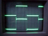
As I remember; I looked with my old 20Mhz scope (Hameg) from 1hz to 200Khz from sine waves to square waves from low to full power and all looked about the same to me. They even clipped the same regardless of the frequency
The only difference was in amount of power and the loss of dB because of the higher frequency. All into 4 ohm and 8 ohm power resistors.When using a square waves the rising and lowering times of the squares looked the same at 1khz 10Khz and 100Khz... I use 10pF instead of the 5pF. With 5pF I got overshoot on the square wave.
Edwin
Thanks Edwin, I just ordered 12 X 47.000µF 40V 154 types from BC.Edwin Dorre said:
I use 6 times 22000uf 63V BC Components type 154 elco's per channel. In a CRCRC with each R=0.11 ohm 20W (4 per channel) .
Together with 8 X 0.1ohm 25W resistors.
I took the 47.000 because they have the best Farad/money value.
I'll keep you informed.
grataku said:Netlist and/or Edwin
did you guys look at the output of the amp using a scope? If so how does the waveform look in proximity to clipping at say 10 kHz looks vs. at 1 kHz?
Grataku, what waves would you like? Squarewave to see the pattern, or sinewave to see the clipping? Or both?
/Hugo - will take some pictures.
Hugo,
I don't recall getting any emails from you, is it something we can discuss here or do you want to try again?
Thanks for taking the time with the pictures and all, it's very helpful.
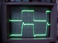
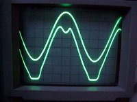
The reason why I asked about the waveforms is because of the strange clipping with sharp 'features' I am seeing at and above ~10kHz/8ohms.
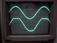
At 1 kHz I would say my sinusoid looks a little bit cleaner than yours. But in general it's pretty much the same. It basically looks like the little singularity you see on your top wave at the right edge where the flat edge meets the sine waveform.
Could this be a characteristic that is intrisec of two stage designs where the distortion increases enormously close to clipping? I don't know I am asking.
One piece of good news I can give you is that the clipping I see in your 1 khz/8ohms sinewave could be made alot more symmetrical and the distortion in the bottom half could be substantially reduced by putting pots in place of the sensing reistor like edwin did and adjusting away. I did the experiment. Maybe I am too optimistic.
If I can make another observation, the square wave could improved by adding an additional 5pf in the feedback, that should kill the ring down you are seeing.
When the board was made we should have probably built in the feedback caps as traces, that way, symmetry in the phase behavior of the feedback would have been closer, we didn't know enough at the time and chad and I where too eager to print out those 800 boards. I did make my feedback network using a pair of 5pf silvermica per side and I did match them up.
I don't recall getting any emails from you, is it something we can discuss here or do you want to try again?
Thanks for taking the time with the pictures and all, it's very helpful.
The reason why I asked about the waveforms is because of the strange clipping with sharp 'features' I am seeing at and above ~10kHz/8ohms.
At 1 kHz I would say my sinusoid looks a little bit cleaner than yours. But in general it's pretty much the same. It basically looks like the little singularity you see on your top wave at the right edge where the flat edge meets the sine waveform.
Could this be a characteristic that is intrisec of two stage designs where the distortion increases enormously close to clipping? I don't know I am asking.
One piece of good news I can give you is that the clipping I see in your 1 khz/8ohms sinewave could be made alot more symmetrical and the distortion in the bottom half could be substantially reduced by putting pots in place of the sensing reistor like edwin did and adjusting away. I did the experiment. Maybe I am too optimistic.
If I can make another observation, the square wave could improved by adding an additional 5pf in the feedback, that should kill the ring down you are seeing.
When the board was made we should have probably built in the feedback caps as traces, that way, symmetry in the phase behavior of the feedback would have been closer, we didn't know enough at the time and chad and I where too eager to print out those 800 boards. I did make my feedback network using a pair of 5pf silvermica per side and I did match them up.
The little AX I built is running around 12V Rails,
Measured 17-watt at zero clipping.
Saw a slight overshoot at 10Hz on the square wave.
Distortion measured around .1%,
I finally worked out my hum issues.
I am running sepeate power supplies for each channel,
CrCrC 110,000uF for the C's and .1-ohm for the r's
It turns out most of my hum issues where grounding related.
I started off having both power supplies connected to a common ground which was connected to the earth ground.
Turned the amp on and instant hum.
Disconnected the earth ground, the hum is still there.
Next I decied to keep the two power supplies grounds isolated from each other with no earth ground.
Turned the amp on with no input connections and all is quiet.
Make the unbal input connections, the hum is back.
Soon it dawns on me that the grounds have their ground loop path back via the RCA connectors and the metal chassis.
I found some insulated RCA connectors to keep the grounds isolated and all is well, no hum.
I currently have my Sutherland 12dAX7 preamp feeding the little AX in my office and it never sounded better.
Thank you all
Netlist said:10Khz 4ohm
Hi,
try to raise the capacitor to 10pF ! You can do this by putting two of your 'old' capacitor in parallel. So if you have them flying around it is worth a try. Your square wave will clean up with this higher value! No ringing whatsoever ...
Edwin
Somehow I missed this post. I can’t recall seeing it yesterday.SisterOfMercy said:
And yes, they would probably be much more expensive. I don't know if it's worth it, but if you really want a low impedance of your power supply, that's one way to do it..
Thanks Sister, I came to the same conclusion but the price of those 114,115 is a bit excessive.
As Edwin stated, his PSU is dead silent with the 154-series, so I’ll give it a try.
The difference in price is € 224 for 2 amps!!
The squarewave in the 10Khz and up region can be better and I will work on that. Nevertheless, the amp sounds great.weeghel said:Netlist: How would you qualify these results?
Also: I sent you a message through the forum yesterday, did you receive that?
I replied to your mail. Basically, a schematic will be posted as soon as I am completely satisfied with all resistor and other values.
grataku said:Hugo,
I don't recall getting any emails from you, is it something we can discuss here or do you want to try again?
The reason why I asked about the waveforms is because of the strange clipping with sharp 'features' I am seeing at and above ~10kHz/8ohms.
Well, we must conclude the email system doesn’t work.
Anyway, it was about the cheaper IRF’s at RS-components.
Mail me.
As stated above, the ringing will be improved. I will play with different values of ‘real’ capacitors. I would love to do it without cap. I remember a post from Nelson saying something about removing the caps in the XA200. How does he get a clean square without cap? Or would there be other tricks?
The active part of the CS is now set at +/-55%. I’ll try different values for that as well.
But first of all, the PSU will be rebuild. (maybe today or tomorrow)
Thanks to you all for the help.
/Hugo
Dear Netlist,
I am really happy that somebody took the time to measure the aleph-x as some time I did but the responce was minimal. However, I would like to ask at what power output levels did you take the measurements you post, and upon what kind of load(inductive, resistive, mixed etc)? Did you tried loading the output with 1-2uf?
What is peculiar is that I faced the similar problematic and discouraging measurements with my aleph and I really could not digest these, so I after much search I gave up and postponed the construction of my aleph-x, although I have all the parts in hand. my measurements
Netlist said:
Somehow I missed this post. I can’t recall seeing it yesterday.
Thanks Sister, I came to the same conclusion but the price of those 114,115 is a bit excessive.
As Edwin stated, his PSU is dead silent with the 154-series, so I’ll give it a try.
The difference in price is € 224 for 2 amps!!
I'm a fairly new member, and am still under moderation (maybe not anymore with this post). So it showed up a little later..
I know the price difference can be quite large. The speakers I am currently building (2.5 way) have a crossover that costs in components 150 euro per piece. I could stick lesser quality components in, but I am a whiner who always whines about high quality..
blah blah blah...
- Status
- This old topic is closed. If you want to reopen this topic, contact a moderator using the "Report Post" button.
- Home
- Amplifiers
- Pass Labs
- Industrial AlephX High Power version