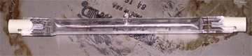
jag said:How about using one (or more) of these 500W (~= 30ohm) light bulbs...
Great way to brighten up a room. I would worry about the lifetime of these bulbs when running at lower power.
--
Brian
There are 2 problems with halogen bulbs:
-the ceramic contacts are absolute and I mean ABSOLUTE crap. The end will cramble away leaving the bare metal contact which will quickly fall off.
-these lamps emit harmful short wave UV (short enough). You need some type of filter.
-the ceramic contacts are absolute and I mean ABSOLUTE crap. The end will cramble away leaving the bare metal contact which will quickly fall off.
-these lamps emit harmful short wave UV (short enough). You need some type of filter.
Thanks for reviving one of my favorite topics:
The Halogen action ceases at lower power levels, and they
become ordinary filament lightbulbs.
(research credit to Cyclotronguy, back when Zenlite was
being created.)
Also, at lower power levels UV is not much of a
concern.

BrianGT said:Great way to brighten up a room. I would worry about the lifetime of these bulbs when running at lower power.
The Halogen action ceases at lower power levels, and they
become ordinary filament lightbulbs.
(research credit to Cyclotronguy, back when Zenlite was
being created.)
Also, at lower power levels UV is not much of a
concern.
till said:Anybody out there?
would be 300*40mm 500wdg 1^2 ok??
Sorry, Just got back from Tuva.
Yes, I believe it would be OK.
Keep away from OUR wives then!Jakeh said:Following in Feynman's footsteps, Nelson?

Graham, do you mean watch out for Nelson making a Pass at your wife ?.Circlotron said:
Keep away from OUR wives then!
Eric.
The idea of using an inductor for the current source appeals
to me except for the large size needed. But if used only in a
midrange or tweeter amp would a verry large inductor be needed
or would something in the 20mh range be large enough for use
in a midrange amp.
Just a thaught,
bob12345678
to me except for the large size needed. But if used only in a
midrange or tweeter amp would a verry large inductor be needed
or would something in the 20mh range be large enough for use
in a midrange amp.
Just a thaught,
bob12345678
Now your'e thinking!!!
What a superb idea!. Or, how dumb I am by comparison. Why didn't I ever think of that? It's just like the situation with a tube output tranny - the lower the frequency or the higher the level you want to go, the more iron and inductance you need. The way I understand it, the greater the area under the half cycle of signal (because of either signal time or level or both) the further the core is going to be momentarily magnetised in that direction. Therefore you need more meat in the core to support it. If you assume you need the same output voltage swing at all frequencies from each of your low, mid and high amps then the required inductance should be inversely proportional to the lowest frequency handled by each.
This is great news! Allied signal make this magnetic material called Metglas Powerlite that is formed from really thin 25uM foil-like strips of mettalic stuff that are often used for inductors in he-man size switchmode psu's. http://www.elnamagnetics.com/metglas/powerlite.htm They look like C-core tranformers. They have low losses to 100kHz or more while handling kilowatts. This looks like worth investigating for an output choke for a mid or tweeter amp. Naturally you would have to gap it to allow for dc magnetisation. I have one in the junkbox, I'll have to give it a go.
What a superb idea!. Or, how dumb I am by comparison.
Why didn't I ever think of that? It's just like the situation with a tube output tranny - the lower the frequency or the higher the level you want to go, the more iron and inductance you need. The way I understand it, the greater the area under the half cycle of signal (because of either signal time or level or both) the further the core is going to be momentarily magnetised in that direction. Therefore you need more meat in the core to support it. If you assume you need the same output voltage swing at all frequencies from each of your low, mid and high amps then the required inductance should be inversely proportional to the lowest frequency handled by each.This is great news! Allied signal make this magnetic material called Metglas Powerlite that is formed from really thin 25uM foil-like strips of mettalic stuff that are often used for inductors in he-man size switchmode psu's. http://www.elnamagnetics.com/metglas/powerlite.htm They look like C-core tranformers. They have low losses to 100kHz or more while handling kilowatts. This looks like worth investigating for an output choke for a mid or tweeter amp. Naturally you would have to gap it to allow for dc magnetisation. I have one in the junkbox, I'll have to give it a go.
Mr.Nelson Pass
Nelson Pass said:
Inductors work great. I have built a Zen with a 1 Henry
air core coil (...alright, a spool of magnet wire) and it had
about 40% efficiency and good low distortion. Of course it
has very low resistance, and so the Zen's original bias
network cannot be used to set the DC current
As seen in ZV1, light bulbs work pretty well too, but at much
lesser efficiency.
Nelson Pass said:You bias the circuit at the peak output current, but you
increase the efficiency because the inductor will swing as
much as twice the supply value. thus you approach 50%
efficiency.
The coil was simply a big spool of 16 gauge.
Dear Mr.Nelson Pass.
Fasinated by your way of engineering,i have been thinking to build something like this as the above.With a two big spools.
May I ask what you did use at that time for the bias network?What was the dc-resistance approx?
Maybe you have some guidelines for me,i would be much grateful.
Thank you in forward,Arthur.
ps.I just begun to have a cuppercage around the mosfets on the heatsinks...see attachm.
Attachments

toroid choke
Hi again!
Afther 2 years I would like still try to build an inductor loaded Zen, the ZV8.
I find a little workshop (toroid transformator maker), where I could winding the chokes.
My plan is that I will make a ca. 300VA toroid trany, but with only primary windings. (min. 100mH 0.5 Ohm 2A)
My question:
Should I use only one torroid core with two separated primary windings or need I 2 separated core with 1 primary windings on each??
I don't know is there any "crosstalk-saturation" problem between the two primarys in one core?
Greets:
Tyimo
Do you mean an inductor between the + supply and the Drain
of the Mosfet? If so, only a single coil is required per channel,
and you could consider simply buying a roll of magnet wire. As
I think I indicated, a several hundred foot roll of 16G magnet wire
(MWS is a good brand) will work great.
In case you were exploring using 1 core for 2 channels, the
answer is no.
Thank You Mr.Pass!
Yes, I mean an inductor between the + supply and the Drain
of the Mosfet.
I know You have built a Zen with a 1Henry coil (a 1000 foot spool of MWS magnet wire).
But, hasn't got too much resistance of this roll of 16G magnet wire coil?
My plan was that I would make something similar that You used with the ZV7T : an ordinary AC power transformers like the 300 VA Plitron toroidal transformer, but with only two and separated primary windings.
Thanks for your answer again.
Greets:
Tyimo
- Status
- This old topic is closed. If you want to reopen this topic, contact a moderator using the "Report Post" button.
- Home
- Amplifiers
- Pass Labs
- Inductors, Lightbulbs As Current Sources