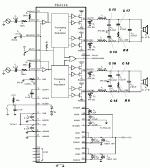
I've gone through the technical notes for the TA2024, especially the schematic for the TA2024 mini, if we are to connect the 12v+ directly to the positive pins of the the 2 electrolytics, I'm just wondering if by doing so, will both VDDA (pin 33) and CPUMP (pin 36) be still supplied with the required 12v+? If not, what remedy is needed to feed the 12v+ to these pins? As per the TA2024 mini schematic, VDDA is attached directly to 12v+, while CPUMP is connected to a 1uf cap then to the 12v+ line. Thanks for taking time on this inquiry. 
D0Hbert said:I've gone through the technical notes for the TA2024, especially the schematic for the TA2024 mini, if we are to connect the 12v+ directly to the positive pins of the the 2 electrolytics, I'm just wondering if by doing so, will both VDDA (pin 33) and CPUMP (pin 36) be still supplied with the required 12v+? If not, what remedy is needed to feed the 12v+ to these pins? As per the TA2024 mini schematic, VDDA is attached directly to 12v+, while CPUMP is connected to a 1uf cap then to the 12v+ line. Thanks for taking time on this inquiry.
Yes, connect the 12V there. There is no need to considering the schematics / datasheets because unless you start cutting traces, you are not altering the fact that all subcircuits that had 12V were still common to each other. You could literally connect your 12V supply _anywhere_ you measured 12V previously and it'd work fine- but it'll work even better (at least theoretically moreso than in practice) if you use a short lead from power supply and connect it inbween those two electrolytics as posted in the prior picture.
Its a pitty the T-amps have such an unpractical input stage which forces you to use a coupling cap. I have the 1B myself and have put a 22uf cap at the input. It works ok with a passive preamp but gain is a bit on the low side. They should have put the input on the non-inverting side so you could change the gain but keep your input Z high and direct coupling. Caps in the soundpaths are horrible. Ok when new but the sound worsens very rapidly after a year or 2, becomes less involving.
Extra Caps to Tripath Design.
I have just noticed some extra Caps on the SI board on the output side..They are C22 & C23. They are in parallel
with 2 of the 0.47uf (if they are that value) output caps, C 14 & C15 ? (see previous picture).This must have some effect.. Any ideas? Also what are C19 & C20 ?
Barry.
I have just noticed some extra Caps on the SI board on the output side..They are C22 & C23. They are in parallel
with 2 of the 0.47uf (if they are that value) output caps, C 14 & C15 ? (see previous picture).This must have some effect.. Any ideas? Also what are C19 & C20 ?
Barry.
D0Hbert said:Actually, you don't have to remove the inductors, after removing the supply cap, you can place the bigger cap from underneath the board so there's no hindrance in the placement of the cap, just make sure positive leg is towards the chip.
Thanks Dohbeert, this makes sense
Re: input caps
This subject has been beat to death on several threads including,
http://www.diyaudio.com/forums/showthread.php?s=&threadid=58873&perpage=25&pagenumber=1
Try doing a search and see what comes up. Lots of good information to be found.
Roger
deiksac said:Perhaps this has already been answered somewhere - can i use non polarised foil caps at the input or am i obliged to use electrolytics?
This subject has been beat to death on several threads including,
http://www.diyaudio.com/forums/showthread.php?s=&threadid=58873&perpage=25&pagenumber=1
Try doing a search and see what comes up. Lots of good information to be found.
Roger
Re: input caps
Yes, and it is the preferred arrangement since (the typically recommended 2.2uF) it's reasonably attainable with film caps.
deiksac said:Perhaps this has already been answered somewhere - can i use non polarised foil caps at the input or am i obliged to use electrolytics?
Yes, and it is the preferred arrangement since (the typically recommended 2.2uF) it's reasonably attainable with film caps.
One more thing - the diodes at the output have to be schottky type? Or can i get along with some fast types such as http://www.ortodoxism.ro/datasheets/philips/BYV27_4.pdf - BYV27-200 ?
A friend of mine noticed that there is in fact just the voltage drop difference; I am not very profficient in circuit theory so can't imagine how the amp will behave.
A friend of mine noticed that there is in fact just the voltage drop difference; I am not very profficient in circuit theory so can't imagine how the amp will behave.
Schottky?
There is more than just the diode speed issue here, as you noted the Schottky's typically have a lot less forward voltage drop. A standard fast recovery diode can have 3 times more. This sets the value for how much reverse voltage the output device can see. This would also have a direct bearing on recovery time for this device due to stored charge in the gate being higher with this higher voltage. A slower turn on would be the result causing higher distortion.
Roger
deiksac said:One more thing - the diodes at the output have to be schottky type? Or can i get along with some fast types such as http://www.ortodoxism.ro/datasheets/philips/BYV27_4.pdf - BYV27-200 ?
A friend of mine noticed that there is in fact just the voltage drop difference; I am not very profficient in circuit theory so can't imagine how the amp will behave.
There is more than just the diode speed issue here, as you noted the Schottky's typically have a lot less forward voltage drop. A standard fast recovery diode can have 3 times more. This sets the value for how much reverse voltage the output device can see. This would also have a direct bearing on recovery time for this device due to stored charge in the gate being higher with this higher voltage. A slower turn on would be the result causing higher distortion.
Roger
optimum ground?
Hi @If and everyone else!
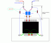
I'm playing around with the optimum ground points for the inputs and wondered which/where is best?
The post shows a connection to the output ground as an option, is this a good idea?
What have other people done?
Cheers
Lee
@lf said:... option...
Hi @If and everyone else!
I'm playing around with the optimum ground points for the inputs and wondered which/where is best?
The post shows a connection to the output ground as an option, is this a good idea?
What have other people done?
Cheers
Lee
Attachments
- Status
- This old topic is closed. If you want to reopen this topic, contact a moderator using the "Report Post" button.
- Home
- Amplifiers
- Class D
- Inductors in T Amp

