
")
I figured to get very far quickly you'd be in for a good bit of what's in the last picture.
I actually downloaded the IR2110 model from IR yesterday. I'll probably plug the rest in sometime. I just have a lot of questions I don't want to bother you with, since you're probably in the mood for answers lately. I've never used these driver ICs. In a bit of a time crunch this week though..
I actually downloaded the IR2110 model from IR yesterday. I'll probably plug the rest in sometime. I just have a lot of questions I don't want to bother you with, since you're probably in the mood for answers lately. I've never used these driver ICs. In a bit of a time crunch this week though..
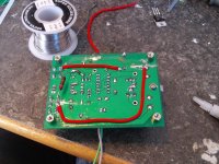
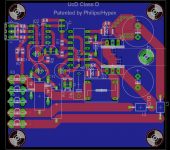
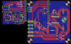
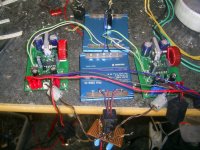
Just like suggested, this change in the layout has no effect what so ever on the AM interference. I guess this means it could actually be the output filter inductor alone.
I bodged it up on one of the modules for testing:
Like i said. your output inductor is sitting perpendicular to your signal processing section.
The leakage flux from a toroid is not like a solenoid. Well it is, but like the solenoid core axis was rotated 90 degrees, to align with the toroid diameter and in 30 positions at once. (for a 30 turn, even, single layer winding, that is). .. mainly canceling at short distances if the winding is even.
I don't think it is the position of the inductor that's his biggest problem, although as I said, I would hand wind it very evenly and fully shield it just because it is possible.
He doesn't have any signal lines running right under the inductor or anything.
I don't think it is the position of the inductor that's his biggest problem, although as I said, I would hand wind it very evenly and fully shield it just because it is possible.
He doesn't have any signal lines running right under the inductor or anything.
Last edited:
I replaced the toroid inductor with one of these that is used on the L25D modules by LJM/sure/IR, also this with no change or even more junk on AM, its almost as if the original unmodded version produced the least amount of interference, as i can now find the thing on even the fundamental and several harmonics up as where the original only showed up at second and third harmonic.
Now we do not have any stations on AM anymore where i live so i do guess this might make the tuner extra sensitive as there are no stations to dilute AM reception/drown out the EMI from the classd module.
But as the Hypex and Abletec modules can run right beside a AM tuner without any kind of interference(wouldent pass EMC testing otherwise), this is the goal for my diy as well, ie pass EMC testing if i had such money to afford it.
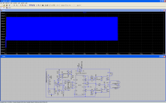
I'm trying to help, not ask boring questions, but have you looked at all your switching waveforms to first make sure the the thing is actually operating as you imagine? No shoot-through, no ringing.. With all the radiation it's likely something unusually fast and high current is going on, because you don't have much of an teansmitting antenna to work with.
D
Deleted member 148505
So i halved the 22k feedback resistor to 11k and added a 100ohm resistor between the 3.3V psu and the two 680ohm resistors on the levle shifter and the noise floor went down ALOT! Both modules are now running together and theres so little noise that unless im right in front of the speakers i cannot hear the noise over the pc.
Attachments
Hi Tekko,
Regards
MANOJ
Did you increase the value of 680R to 2k2 with parallel 15pF capacitorthe two 680ohm resistors on the levle shifter
Regards
MANOJ
And noise floor has been dropped substantially compared to before, a 1nF cap across the audio input did alot along with some clip on ferrites on the audio inputs.
Removing the ferrites on the gate drive wires also lowered noise. Including all psu wires within the same ferrite also helped lower noise.
Removing the ferrites on the gate drive wires also lowered noise. Including all psu wires within the same ferrite also helped lower noise.
And noise floor has been dropped substantially compared to before, a 1nF cap across the audio input did alot along with some clip on ferrites on the audio inputs.
Removing the ferrites on the gate drive wires also lowered noise. Including all psu wires within the same ferrite also helped lower noise.
ferrites on the gate drive wires? how did you obtain the inductance value for the gate drive ? of course im assuming you didn't randomly throw a inductor with calculation or modeling RLC series?
IE on the gate drive psu wires, not the gate wires themselves.
The only noise i can hear from this setup, is a very faint metallic ringing kinda noise which most likely caused by the blue DC/DC modules, i can hear audible noise emanating from those.
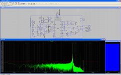
This is the current schematic.
The only noise i can hear from this setup, is a very faint metallic ringing kinda noise which most likely caused by the blue DC/DC modules, i can hear audible noise emanating from those.
This is the current schematic.
Attachments
IE on the gate drive psu wires, not the gate wires themselves.
The only noise i can hear from this setup, is a very faint metallic ringing kinda noise which most likely caused by the blue DC/DC modules, i can hear audible noise emanating from those.
This is the current schematic.
oh the gate drive IC, normally its powered from a voltage regulator which has good ripple rejection (with decoupling at the in and out pins)
- Status
- This old topic is closed. If you want to reopen this topic, contact a moderator using the "Report Post" button.
- Home
- Amplifiers
- Class D
- Increased noise with multiple modules