Hi folks,
I'm busy trying to understand fetdriving.
I tried something in Multisim v10.0
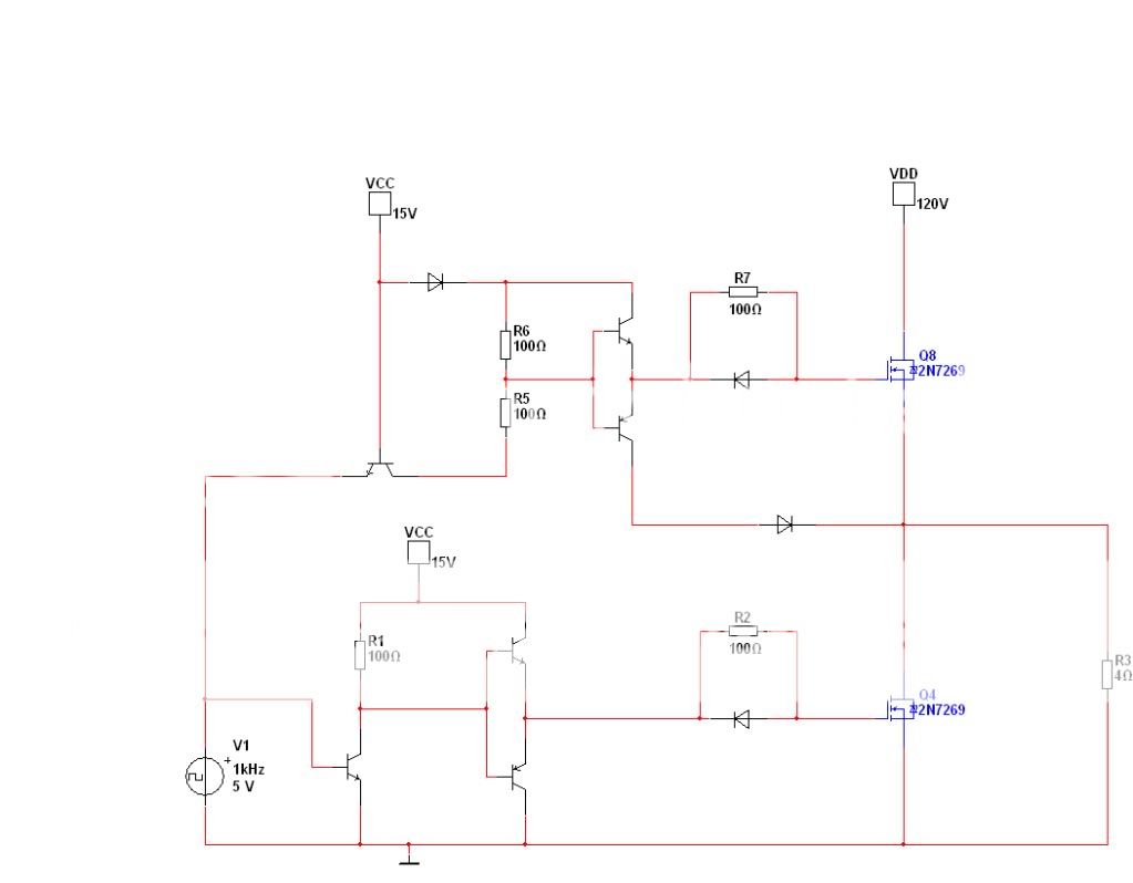
This seems to work a bit, but the highside does have a lower amplitude as the lowside.
Any suggestions how to improve this schedule, or which schedule to use otherwise?
My class D is single supplied with 120Vdc.
I have to get 1500W in a 4ohm load.
I'm not a very experienced user of class D equipment, so please try to explain things simple.
I'm busy trying to understand fetdriving.
I tried something in Multisim v10.0
This seems to work a bit, but the highside does have a lower amplitude as the lowside.
Any suggestions how to improve this schedule, or which schedule to use otherwise?
My class D is single supplied with 120Vdc.
I have to get 1500W in a 4ohm load.
I'm not a very experienced user of class D equipment, so please try to explain things simple.
Firs of all: the supply for the high side FET should be floating!
The level shift also bad, see some application notes first.
Where should the - of the floating supply connected?
And where do I find decent application notes?
I found some application notes, but they're not to helpfull
If I understood you guys right, this should be an improvement,
Though I can't find anything about the 'bad-biasing' you spoke about.
I found some application notes, which are poorly explained and because of that not to helpfull.
The only thing I got from those apllication notes, is seeing that they use 2 FETs instead of BJTs.
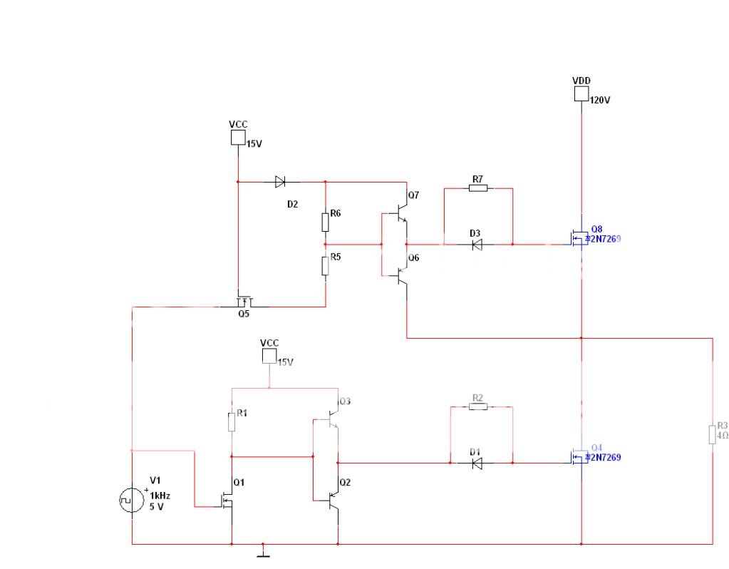
The schedule with some adjustments.
Though I can't find anything about the 'bad-biasing' you spoke about.
I found some application notes, which are poorly explained and because of that not to helpfull.
The only thing I got from those apllication notes, is seeing that they use 2 FETs instead of BJTs.
The schedule with some adjustments.
Where should the - of the floating supply connected?
And where do I find decent application notes?
I found some application notes, but they're not to helpfull
Read this:
http://www.ti.com/lit/ml/slup169/slup169.pdf
From page 22 starts the bootstrap drive.
Thank you for that link, there is quite some usefull information in it, though I have no clue how to implement it into my schedule.
I also checked the IR2011, which seems easier to get working in a practical situation.
I'll be busy for a bit with the new information for a while, if I encounter more problems I will post them right away.
Class D is still witchcraft to me afterall.
I also checked the IR2011, which seems easier to get working in a practical situation.
I'll be busy for a bit with the new information for a while, if I encounter more problems I will post them right away.
Class D is still witchcraft to me afterall.
Though I can't find anything about the 'bad-biasing' you spoke about.
In the first circuit, base is more positive than collector, so it has no room to amplify, then upper MOS is not well drive.
Thank you for that link, there is quite some usefull information in it, though I have no clue how to implement it into my schedule.
I also checked the IR2011, which seems easier to get working in a practical situation.
I'll be busy for a bit with the new information for a while, if I encounter more problems I will post them right away.
Class D is still witchcraft to me afterall.
Read, Read and Read more... until it's is aint witchcraft.
Read, Read and Read more... until it's is aint witchcraft.
I will for sure, I think the first knowledge is starting to come:
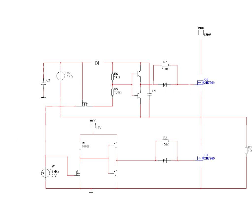
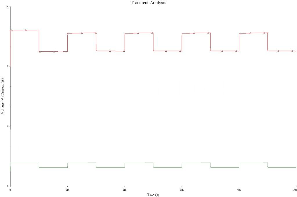
Simulation of Loadvoltage and Loadcurrent
Read, Read and Read more... until it's is aint witchcraft.
I'm reading a lot at this moment and found the IRS20124 as an option.
I'm trying to find out if I can get the IRS20124 to drive a 1500W in 4 ohm class D amp. (single supply 120 Vdc)
Which parameters are important and where do I find information about this?
Datasheet: http://www.irf.com/product-info/datasheets/data/irs20124s.pdf
Last edited:
I'm reading a lot at this moment and found the IRS20124 as an option.
I'm trying to find out if I can get the IRS20124 to drive a 1500W in 4 ohm class D amp. (single supply 120 Vdc)
Which parameters are important and where do I find information about this?
Datasheet: http://www.irf.com/product-info/datasheets/data/irs20124s.pdf
First, the output voltage that the device is capable to sustain, = or > to the 120V in this case.
Second, the velocity of the device is compatible with switching frequency (Which also depend on the FET input capacitance, the voltage swing at the gate and the output current sink/source rates or this device. The more current, normally, the quickest, and greater the input FET cap and gate voltage, the slower the switching times.
Third, in your conditions, the internal power dissipation capability.
So let's see,
This device can be supplied up to 200V and operates up to 1MHz.
The maximum highside output is the Vb (max 220V) + 0.3V
Vb = Vs + Vcc = 200V + 20V (maximum ratings)
My maximum frequency is 200KHz.
Maximum Power dissapation = 1.25W
The thermal resistance (junction-ambient) = 100 C/W
The maximal junction temperature is 150 C
Seen the graphs in the datasheet, the temperature will be somewhere between 35 and 45 C, depending on the gateresistance.
How do I calculate if those 'thermal' speccs are good enough for my design?
Last edited:
So let's see,
This device can be supplied up to 200V and operates up to 1MHz.
The maximum highside output is the Vb (max 220V) + 0.3V
Vb = Vs + Vcc = 200V + 20V (maximum ratings)
My maximum frequency is 200KHz.
Maximum Power dissapation = 1.25W
The thermal resistance (junction-ambient) = 100 C/W
The maximal junction temperature is 150 C
Seen the graphs in the datasheet, the temperature will be somewhere between 35 and 45 C, depending on the gateresistance.
How do I calculate if those 'thermal' speccs are good enough for my design?
Appears to be OK for the job you are wanting for it. Check output device current capability (Source and sink to gate pin of MOSFET). As high are these currents, as quick it can switch transistors and lower the output stage
temperature, but have in mind it is at the cost of more supply current into this device. Also be careful in the coupling network and wiring from output of the driver and the gate MOS Power. Use broad and short traces, so minimize inductances and resistances in the tracing, also reduce as you can capacitive coupling between drain and gate traces. I may suggest a pdf called "AN-936:
The Do's and Don'ts of Using MOS-Gated Transistors" at International Rectifier site, and "SLUP169" in TI web site. In the last, pay special attention to fig 31 and the text associated.
Thank you again, I've read both application notes by now. The currents are high enough for my shiftingfreuency (1A sourced and 1.2A sinked).
Seems I need to do some research on a good feedback network now. I think I have it now for the fetdriver. Would you recommend the PowerFETs of IRF?
I have a few options which include IRF, Silicon Labs and Philips.
Seems it's gonna be the IRFB5620.
Qg = 25nC, And with a drivercurrent of 1A, the transitiontime = 25ns.
If I'm correct device won't overheat under my operationrequirements.
Datasheet: http://www.irf.com/product-info/datasheets/data/irfb5620pbf.pdf
Would you recommend the PowerFETs of IRF?
I have a few options which include IRF, Silicon Labs and Philips.
I have personal preferences about ST Microelectronic products, but it is only a personal taste. In the past, UC3842 and STP7N60 made by ST, works very fine in SMPS at PC monitors, a good couple, while Unitrode or TI have failed by lots.
Also, IR is a good supplier and LT, but I don´t know if it produces Power FET´s.
And with respect to feedback networks, several time ago I did my own project, that in the protoboard worked excelent, but at the moment of make the PCB it several times failed, I could´t know why. I may suggest more interesting readings: a work titled "From the book Introduction to Electroacoustics and Audio Amplifier Design, Second Edition - Revised Printing, by W. Marshall Leach, Jr., published by Kendall/Hunt, °c 2001.) (I have not the original pdf name, but is the best I found in the time I was developing mine), and " Simple Self-Oscillating Class D Amplifier with Full Output Filter Control , by Bruno Putzeys" (Idem comments, but google for them).
Good luck, and keep un posted !!!
Last edited:
I have personal preferences about ST Microelectronic products, but it is only a personal taste. In the past, UC3842 and STP7N60 made by ST, works very fine in SMPS at PC monitors, a good couple, while Unitrode or TI have failed by lots.
Also, IR is a good supplier and LT, but I don´t know if it produces Power FET´s.
And with respect to feedback networks, several time ago I did my own project, that in the protoboard worked excelent, but at the moment of make the PCB it several times failed, I could´t know why. I may suggest more interesting readings: a work titled "From the book Introduction to Electroacoustics and Audio Amplifier Design, Second Edition - Revised Printing, by W. Marshall Leach, Jr., published by Kendall/Hunt, °c 2001.) (I have not the original pdf name, but is the best I found in the time I was developing mine), and " Simple Self-Oscillating Class D Amplifier with Full Output Filter Control , by Bruno Putzeys" (Idem comments, but google for them).
Good luck, and keep un posted !!!
I'd already read a work titled "From the book Introduction to Electroacoustics and Audio Amplifier Design, Second Edition - Revised Printing, by W. Marshall Leach, Jr., published by Kendall/Hunt, °c 2001. That was called The Class-D Amplifier and is found under the link http://users.ece.gatech.edu/mleach/ece4435/f01/ClassD2.pdf
I can't find the piece written by Bruno Putzeys though, I can only find references to that piece.
I'll be using a differential amplifier as feedback. If you look at page 4 you'll find figure 7 which is an schedule of such a system. I noticed one problem with that schedule: 2 stages with capicitance, which means 2x 90 degrees phaseshift. That would create an oscillator. I can easily calculate the oscillationfrequency, but it gives a risk to have an oscillator in my feedback. If I replace Cf with an resistor I would remove the oscillation and could controll my loopgain with the value of that resistor. Is this thinking correct?
Last edited:
Send me an email to oszappa@yahoo.com or oszappa@gmail.com, I´ll send it attached.
- Status
- This old topic is closed. If you want to reopen this topic, contact a moderator using the "Report Post" button.
- Home
- Amplifiers
- Class D
- Incorrect fetdriving?