This is how I see it. Power compression is something you really have to measure. It's temperature rise of the coil. When copper gets hot, its impedance goes up so less current is drawn and less sound is made. I wish manufacturers would chart this stuff. Unfortunately, IEC-60268-5 doesn't lists a specification for it. Some drivers just don't care when you go over, they just don't get louder, but don't melt for quite a ways to go. Other cheap POS ones, fall over the cliff and keep getting quieter because they can't dissipate.
The only thing I know about how the cabinet can affect PC is if the rear chamber is too small. It affects the way heat isn't dissipated. The Lab subwoofer had this problem when people tried operating it below Fc with a small rear chamber to compensate for excursion. They made a new problem: greater heat and/or less capacity for the driver to dissipate it.
Power compression can be measured by doing sine sweeps at differing levels and overlaying the graphs subtracting the gain change to observe where the compression effect is taking place. I used a sound system meter once that would run a test and would give me the 1dB compression point as a drive voltage. I wished I owned it, it was quite nice.
If the power limit of the 2226J is accepted as 400W before 1dB of PC, and the driver is 8 Ohms, that puts Eg at 56.57V.
The prior incarnation of my mid-bass cabs I would run on 800W amps. It was a little over the music power rating of 600W for the two drivers together in parallel. I never was blessed to have measured them.
don't stop there, DavidIs HR assuming assuming a horn that is square shaped progression where the wall widths are equal?
Hi davygrvy,
I had originally thought that you were referring to the way in which Hornresp calculates directivity response, but from your question above, I am not so sure of that anymore
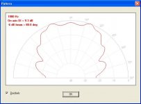
. If you can clarify for me what is meant by "squared shaped progression" and "wall widths are equal", I will attempt to provide a specific answer.As far as directivity is concerned however, unlike AkAbak (which uses the concept of a "radiation cone") Hornresp takes the actual contour of the flare into account. As can be seen from the attached screenprint examples, a conical horn has quite different directivity characteristics to an exponential horn having the same S1, S2 and L12 values.
Kind regards,
David
Attachments
the info given by HR (SPL, excursion, etc) is based on cone theory.. but isn't it true that the science (being based on the areas of the throat, exit, segment length, etc.) does not change when you mangle the cone a little bit?
Looking forward to David's answer on this as well
Hi letsbangout,
Not sure I understand what you mean by "cone theory" - could you please clarify.
Kind regards,
David
Hi davygrvy,
I had originally thought that you were referring to the way in which Hornresp calculates directivity response, but from your question above, I am not so sure of that anymore
Thanks David. For the directivity shot of the conical horn, are you displaying vertical or horizontal? That's really my question.. If we export the progression and modify the shape, but keeping the same progression (cross-sectional area over distance) to fit our box that say might be wider than tall, is the directivity now different than what the sim gives us?
For the directivity shot of the conical horn, are you displaying vertical or horizontal?
Hi davygrvy,
By default, Hornresp assumes that the horn is axisymmetric (circular cross-section), so for the previous conical horn example (S1 = 100, S2 = 20000, L12 (Con) = 100), the horizontal and vertical directivity patterns will be the same.
It is possible however, to get a reasonably useful indication of the directivity performance of a rectangular cross-section horn by using the following process:
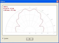
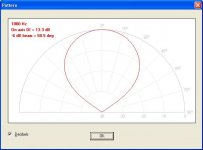
If the example conical flare horn has a square throat 10cm (Hor) x 10cm (Ver), a rectangular mouth 200cm (Hor) x 100cm (Ver) and a length of 100cm:
The horizontal directivity pattern can be approximated using:
S1 = 78.54 (10cm diameter), S2 = 31415.93 (200cm diameter) and L12 (Con) = 100.
The vertical directivity pattern can be approximated using:
S1 = 78.54 (10cm diameter), S2 = 7853.98 (100cm diameter) and L12 (Con) = 100.
The attached screenprints show the horizontal and vertical directivity patterns at 1000 hertz for the above example.
Please note that Hornresp directivity results are indicative only. To get a really accurate prediction, 3-D BEM simulation software or something similar would need to be used.
Kind regards,
David
Attachments

By default, Hornresp assumes that the horn is axisymmetric (circular cross-section)..
Ahh, I thought so. Thanks for the explanation and method.
- Status
- This old topic is closed. If you want to reopen this topic, contact a moderator using the "Report Post" button.