Which commercial brands (except Creek) uses this topology?
None, to my knowledge.
Alex
Hi Kevin,
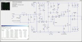
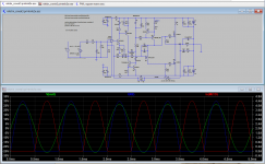
that first circuit could be quite unlinear without a feedback and at low bias currents. However the transfer characteristic is reasonably symmetric between upper and lower halfs. If you increase the bias, the linearity is much better. I attach the simulation circuit and FFT result for 900mA bias 50 V p-p into 8 Ohm - Gain is about 50, THD is under 0.3%. Bandwidth at -3 dB is 300 kHz. The difference of Zout on the phase splitter is not a serious problem, as far as I can see.
Cheers
Alex
Hi Alex
I'm trying to reproduce LTSpice simulations on your circuits. I use the latest LTSpice XVII.
However, I got no luck. For example, I make the circuit identical to your simulation but it doesn't work as expected.
Please help get rid my mistakes?
Thank in advance
Hi @minek123Alex didn't show up on this forum since Sept 2021.
Can you post your sim/models?
Thanks for reply.
Attached is my LTSpice XVII schematic and simple result. It's identical to reply #13 in this thread.
Any help appreciated.
Attachments

He might be unwell..his last post on tapeheads was in june 2021...Alex didn't show up on this forum since Sept 2021.
Can you post your sim/models?
The most popular model where this topology is in use, is Creek's 5350SE - go to schematic in post 4 underNone, to my knowledge.
Alex
https://www.diyaudio.com/community/threads/creek-audio-destiny-help-with-adjusting-vr2.364092/
I've always wondered why the sound quality of this Creek model always seemed poor compared to other amps like Audion (SE with EL34), Pass Aleph, ZEN and first watt series.
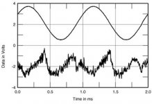
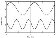
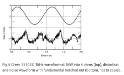
The attached diagrams show the reason clearly - check also the reviews under
https://www.stereophile.com/content/creek-5350se-integrated-amplifier-measurements-part-2
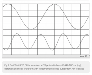
https://www.stereophile.com/content/first-watt-sit-3-power-amplifier-measurements
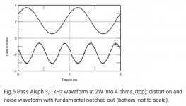
https://www.stereophile.com/content/pass-labs-aleph-3-power-amplifier-measurements
residual distortion and noise waveform character with fundamental notched out speaks a clear language.
The great efforts made in circuit design to improve linearity of N-Ch MOSFET's are apparently not effective, if the quiescent current in the output stage is not sufficiently high (i.e. small value as usual in Class AB).
Attachments
Yes, it poorly rings.As far as handling square waves goes, my model in previous post is a disaster... Not sure if it's fixable...
But I wonder how he did sim for the circuit in post #13. I just can't make it.
In fact, I can't for the first several circuits from his PDF article.
Could you please highlight your correction and reasons?Hello. Slightly changed the correction
Thanks in advance.
Here is an attempt to fix ringing.
I replaced VAS CCS with bootstrap (this is unrelated to fixing ringing), and tweaked some C/R values.
It seems that diodes D3/D4 are primary reason of troubles with square waves.
These changes of course affect Thd results for sinus waves, but perhaps there is a way to make both of them happy..
I wonder if anybody simulated original Creek 4330...
@printnik - I couldn't fix ringing with your compensation RC solution, at least not quickly..
So this is not final/correct solution yet.
Attachments
")
Hi, tiefbassuebertr. Can you elaborate on how the sound quality of the 5350SE is poor compared to Audio, Pass Aleph, Zen and first watt series? Asking because I'm happy owner of the Creek Destiny which is I guess a bigger twin of the 5350SE, and have thought about upgrading to another amp.The most popular model where this topology is in use, is Creek's 5350SE - go to schematic in post 4 under
https://www.diyaudio.com/community/threads/creek-audio-destiny-help-with-adjusting-vr2.364092/
I've always wondered why the sound quality of this Creek model always seemed poor compared to other amps like Audion (SE with EL34), Pass Aleph, ZEN and first watt series.
The attached diagrams show the reason clearly - check also the reviews under
https://www.stereophile.com/content/creek-5350se-integrated-amplifier-measurements-part-2
https://www.stereophile.com/content/first-watt-sit-3-power-amplifier-measurements
https://www.stereophile.com/content/pass-labs-aleph-3-power-amplifier-measurements
residual distortion and noise waveform character with fundamental notched out speaks a clear language.
The great efforts made in circuit design to improve linearity of N-Ch MOSFET's are apparently not effective, if the quiescent current in the output stage is not sufficiently high (i.e. small value as usual in Class AB).
Unless there's a typo, these measurements are inconsistent. Note the 54 watt input for the 5350SE, vs 1 and 2 watts on the other two. Or apologies if I'm missing something here.
Attachments
Last edited:
I tried a couple ideas. One was to use an N-channel MOSFET for M3, which works but suffered a lot from gate voltage loss of clipping amplitude. Then I went back to raising the gate voltage of M3. That has serious positive swing problems unless you add a boosted driver voltage or a bootstrap, but I did get it to swing almost to the rails with a bootstrap. I notice that the diode bypass of M4 exacerbates a very nasty shoot through transient current when clipping, so I changed it to a baker clamp on M4. As usual, using an op-amp is difficult to stabilize so I had to hack your feedback. I just got it to not oscillate and did not do a phase margin check. So this still has issues. But in the spirit of sharing, have a look at these.It wouldn't be quasi, upper and lower half are in opposite phases...
Not sure what is it..
Steve, any idea how to fix it, so it works as intended?
Attachments
Steve, it looks to me that your solution (adding extra bias to M3) corresponds to Alex Nikitin's schematic from page 2 of his document (attached).
After reading this document one more time, I started to think that perhaps solution from post #54 was working correctly? Alex explains in the doc why he didn't go that route.
After reading this document one more time, I started to think that perhaps solution from post #54 was working correctly? Alex explains in the doc why he didn't go that route.
Attachments
If you mean Fig 3: P-ch differential phase splitter, that circuit is biased wrt the rail and not the output, so there is no feedback, more like Elvee's Circlophone etc. Reading the pdf, I see Nikitin talks a bit about the issue of the gate threshold, ie the P-channel threshold has to be (much) higher than the N-channel OP's so that the OP's come on before the P-channels saturate. My solution was to add offset voltage to the P-channel gate to guarantee that happens, but the gate is still driven from the output. It also adds a bit of gain so that the output can slew a bit farther than the VAS, closer to the rails.
Anyway, I am not fond of current driven outputs and long feedback paths. This topology is a lot like the JLH amps which have serious problems like some old NPN only circuits. They are interesting but I don't think I would bother building them today when PNP and P-channel devices are now available at reasonable cost, with the possible exception of class-D amps. However, there are also issues with symmetric IPS amps. The "blameless" topology is well named because it works well and is well behaved.
Anyway, I am not fond of current driven outputs and long feedback paths. This topology is a lot like the JLH amps which have serious problems like some old NPN only circuits. They are interesting but I don't think I would bother building them today when PNP and P-channel devices are now available at reasonable cost, with the possible exception of class-D amps. However, there are also issues with symmetric IPS amps. The "blameless" topology is well named because it works well and is well behaved.
- Home
- Amplifiers
- Solid State
- Improving the linearity of an N-ch MOSFET output stage