BTW, in cases when your feedback divider impedance to output impedance ratio is big, you can use a simplified method, evaluating only a voltage part (if you insert the probe in the right place). It will give a minor error compare to proper Tian or Middlebrook method, but most likely it will be smaller than other inaccuracies in such case. That have to be used with caution, because sometimes it seems it is almost OK but it is really not, but it is almost always fine with audio power amplifiers.
Yes. This was my intent in posts 17 and 18.
The output side of the big inductor faces the OPS which shouldn't care if it's looking at a 56K feedback resistor or an infinite inductor. Impedance at the output node is orders of magnitude lower than 56K. (Even if you run NTE's slowest 2N3055's, the output node impedance is limited to a few ohms at HF by the zobel network.)
The input side of the big inductor faces the feedback divider. That 56K resistor won't care if it's being driven by low-impedance OPS or a 0-ohm AC source. Again, the impedance spread is orders of magnitude.
So this should be a close approximation, within a percent.
You ever have a "breakthrough" where you have something that works, and finally understand why? Well it's one of those days.
The dual-gain feedback loop is related to two-pole compensation (TPC).
Bob Cordell wrote about TPC: "Bode showed that optimal compensation might be had with a 9-dB per octave roll-off (30 dB per decade) instead of a 6dB per octave roll-off (20 dB per decade.) In this case, the phase margin would still be a respectable 45 degree and yet the steeper roll-off would permit much higher gain in the audio band for a given gain-crossover frequency." TPC adds an extra pole and an extra zero to approximate this 9dB/octave roll off.
The dual-gain feedback loop acts similar to TPC. The added R-C in the feedback loop adds 1 extra pole and 1 extra zero, like TPC. This keeps the phase margin near 45 degrees through much of the region between the audio band and the gain-crossover frequency, like TPC.
The 9dB-per-octave behavior is also evident here. While OLG is falling at 6dB per octave (due to normal miller/TMC) the CLG is rising, but more slowly, at around 3db per octave.
The dual-gain feedback loop combines easily with TMC -- can TPC do that?
Last edited:
Yes. This was my intent in posts 17 and 18.
The output side of the big inductor faces
No, it is not what I meant. What I mean you can use just a voltage probe from Middlebrook method with reasonably small error.
Q16 can be replaced by KSA1381 at position Q15
That would increase distortion by several dB. Please see post #2. This extra EF between VAS and OPS reduces distortion, makes an EF2 be almost as good as EF3.
Thanks Dave and Shaq for encouraging me to try Wiedmann's loop gain probe. It really is plug and play.
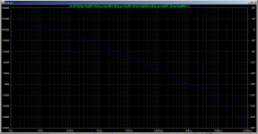
Here's the Tian return chart, using the same circuit from post 18, with the big inductor removed and the probe added at the same location.
Is this the right location? There are two feedback loops, the TMC loop and the global loop. This benign-looking graph locates the probe outside of the TMC loop.
Here's the Tian return chart, using the same circuit from post 18, with the big inductor removed and the probe added at the same location.
Is this the right location? There are two feedback loops, the TMC loop and the global loop. This benign-looking graph locates the probe outside of the TMC loop.
Attachments
35-degree PM at 200KHz on the phase plot in a TPC/TMC design may be sufficiently okay. I have seen a few such designs in this forum that have the phase dip to about -170 before shelving up. It seems as long as the loop gain is kept sufficiently high around that frequency, say, over 60db, to maintain a very low impedance at the output node, there is little chance the parasitics or the load reactance would do damages to the loop stability.
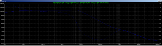
Here's the return ratio plots after locating the loop gain probe inside both TMC and global loops.
The phase lag exceeding 180 is superficially scary. But, it's similar to plots posted here which show that for a typical TMC amp, in-band phase is -90 when probed outside the TMC loop and -180 when probed inside both loops, for the same perfectly healthy amplifier.
I'm tempted to hazard a guess, based on nothing but pattern matching, that the maximum safe phase is -225 when probing inside both loops (with -270 being the point of no return, instead of -180.) If that's true, it would make the phase margin here close to 50 degrees regardless of where we decide to probe.
Attachments
Last edited:
I'm tempted to hazard...that the maximum safe phase is -225 when probing inside both loops (with -270 being the point of no return, instead of -180.) If that's true...
Unfortunately it's not true.
What you have is "conditional stability", search on this and "Nyquist" to learn more.
You are quite close to no stability at all, the amp is likely to oscillate if it clips or from load and component tolerance, power supply variation etc.
Best wishes
David
Can someone confirm if these recent plots Posts 26 & 28...
Is there a way we readers can identify the difference when we see these plots?
I haven't checked every parenthesis and detail but the text at the top of the plots looks like a Tian expression for Return Ratio (AKA Loop Gain).
The plotted data in #28 looks plausible for Two Pole Compensation (so-called) or similar variant (TMC).
The plotted data in #26 looks plausible for a common incorrect position of a probe intended to check TPC/TMC
")
The OP wrote that he used Tian and I would take that on face value since I see no reason to doubt it.
What is your concern?
Best wishes
David
Last edited:
...And then how to interpret...the two different outputs.
Do you mean #26 versus #28 or Open loop versus Return Ratio?
Best wishes
David
...superficially scary. But, it's similar to plots posted here...
Ok, a bit more detailed response.
First, be careful when you read that thread, Damir is excellent with circuits but his use of the term Open Loop Gain looks incorrect in some early posts.
Even native speakers in this forum often mess this up, so no disrespect to Damir.
Someone sorts it out towards the end, maybe read the thread backward.
Also note that Damir's amps are usually unconditionally stable, or close.
Yours has an extensive zone of conditional stability.
#28 shows your amp PM is only 30, Damir usually around 60 or more.
The probe position for your plot #26, if I understand your description correctly, is not useful.
Best wishes
David
And a minor point, Damir calls the floated V source technique a "Middlebrook" probe.
This is a common use but likely to mislead.
Middlebrook only mentioned this method to compare it to his own, superior technique.
Last edited:
Can someone confirm if these recent plots Posts 26 & 28) are loop gain, or open loop gain?
Is there a way we readers can identify the difference when we see these plots?
Both plots 26 and 28 show loop gain measured using Wiedmann's implementation of Tian's method.
Ok, a bit more detailed response.
First, be careful when you read that thread, Damir is excellent with circuits but his use of the term Open Loop Gain looks incorrect in some early posts.
Even native speakers in this forum often mess this up, so no disrespect to Damir.
Someone sorts it out towards the end, maybe read the thread backward.
Also note that Damir's amps are usually unconditionally stable, or close.
Yours has an extensive zone of conditional stability.
#28 shows your amp PM is only 30, Damir usually around 60 or more.
The probe position for your plot #26, if I understand your description correctly, is not useful.
Best wishes
David
And a minor point, Damir calls the floated V source technique a "Middlebrook" probe.
This is a common use but likely to mislead.
Middlebrook only mentioned this method to compare it to his own, superior technique.
Hi David,
Yes I was confused when I started to use LTspice as LTspice educational examples LoopGain lower circuit says Middlebrook and LoopGain2 says:
Here the open loop gain is determined from the closed loop system[1].
The open loop gain can be plotted by plotting the quantity:
and that confused me, but that was long time ago.
BR Damir
...and that confused me...
Hi Damir
Yes, I think that was an error in the documentation, not your fault, thanks for the reminder.
I know you understand this very well, I just did not want anyone else to be mislead by the old thread, there was already sufficient confusion from some of the other contributors
Best wishes
David
Andy_c had a very good introductory lesson of the loop gain analysis using LTSpice here...
http://www.diyaudio.com/forums/software-tools/101810-spice-simulation-87.html
Hope someone may find it useful.
Sa muli,
Albert
http://www.diyaudio.com/forums/software-tools/101810-spice-simulation-87.html
Hope someone may find it useful.
Sa muli,
Albert
took me to post1501 by de OcampoAndy_c had a very good introductory lesson of the loop gain analysis using LTSpice here...
http://www.diyaudio.com/forums/software-tools/101810-spice-simulation-87.html
Hope someone may find it useful.
Sa muli,
Albert
- Status
- This old topic is closed. If you want to reopen this topic, contact a moderator using the "Report Post" button.
- Home
- Amplifiers
- Solid State
- Improving the badger/blameless for ultra low distortion