Peter,
beautiful work indeed!
Only two things i do not like: excessive abuse of PCBs and those {insert unprintable here} RCA plugs bitten right out of the full. RCA plugs are evil anyway but if you use them, use thin sheet metal stuff. You 'll find ones that sound better than any massive stuff, not kidding.
Hollow stuff, not solid stuff")
If i catch up with my REDEL crusading a bit, maybe in 12 months the whole board uses Redel instead. -same as with the MKVs
Harry,
...
beautiful work indeed!
Peter Daniel said:... The input jacks are directly connected from the other side.
I wonder how it all gonna look when I start my p2p, in those days I was firm believer that PCBs are better.
Only two things i do not like: excessive abuse of PCBs and those {insert unprintable here} RCA plugs bitten right out of the full. RCA plugs are evil anyway but if you use them, use thin sheet metal stuff. You 'll find ones that sound better than any massive stuff, not kidding.
Hollow stuff, not solid stuff
If i catch up with my REDEL crusading a bit, maybe in 12 months the whole board uses Redel instead.
-same as with the MKVs Harry,
next time maybe .... when you are not prepared ....Moderator please don't put me in the SIN BIN!
... the proposed design is not optimal
Says you........
If I wanted bipolars and and feedback I would have put them in.
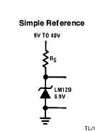
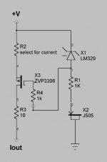
If you put a cap across the LM329 the current source will come up slowly and you will get the turn on thump from hell. This is the third time I have explained this but I will keep explaining and save some poor soul from killing a speaker during power up or down. I put the resistor in series to damp any resonance from the inductive output impedance of the LM329 and capacitance in the current diode or fet use to bias the LM329.
Thanks for your help though......
H.H.
Says you........
If I wanted bipolars and and feedback I would have put them in.
If you put a cap across the LM329 the current source will come up slowly and you will get the turn on thump from hell. This is the third time I have explained this but I will keep explaining and save some poor soul from killing a speaker during power up or down. I put the resistor in series to damp any resonance from the inductive output impedance of the LM329 and capacitance in the current diode or fet use to bias the LM329.
Thanks for your help though......
H.H.
Attachments
Re: when you are not prepared
Harry, you watched "Silence of the Lambs" too often ? (just kidding )
says Hannibal Lecter ...HarryHaller said:I'm ready when you are......
Harry, you watched "Silence of the Lambs" too often ? (just kidding
)Thanks Harry,
Good point. I use output protection circuitry (delayed on, DC sense, extremely fast output relay off-switching, ac-loss detect) so I don't "see" the thump, but it is a good point since this will likely be stressful on the device itself and protection circuits can fail. Perhaps I will consider going with .1uF alone in the future, but there is no way that I personally will forgo without any capacitance in that position.
Another point. If you ever need symmetrical current sources (one on top, the other on bottom), you might want to feed the two voltage sources driving that current device directly between each other instead of to the traditional ground. I have standardized on this approach. I see more and more postings indicating this type of approach, the latest by NP, but in a slightly different scenario.
Different folks, different strokes.
Petter
THUMP!
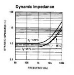
The ap notes shown the noise voltage rolling off above 10kHz and the gate resistor and Mosfet capacitance are going to roll off high frequency noise.
The ap notes show no caps across reference. I believe 0.1uF will still thump a bit. I assume no blame for bent voice coils and jumpy pets and family members......
Attachments
You are right again, HH
And I had forgotten that I have been drawing RC circuits lately as well .... Thanks for reminding me!
Shown with matching negative current source to illustrate that one does not have to go to ground.
The curious 3 resistor setup is what i use in low power situations to get maximum use of each turn, while putting minimum current through the adjustable resistor. I call this "triplets" and there is an excel spreadsheet (using linear optimization) to work out "optimal" values here.
http://diyaudio.com/projects/petter
Petter
Attachments
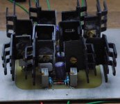
Bauhaus heatsink by petter
Practically abstract sculpture. WAY COOL!!!
http://craton.geol.brocku.ca/guest/jurgen/bauhaus.htm
Practically abstract sculpture. WAY COOL!!!
http://craton.geol.brocku.ca/guest/jurgen/bauhaus.htm
Attachments
Enlightened...
Man, too bad the rating's not based on total words posted... I'd probably top HH on that count. I wonder what my average post lenth is? Err, maybe I don't want to know... heh
Now if only the total number of posts actually did make one enlightened.. I'd be on here every 5 minutes!
Well, good work anyway HH... keep it up!
Don't mock the fool ...
I must admit that building the X100 version 1 (referenced here as an abstract sculpture ) was a bit painful, particularly after I had spent a lot of time essentially compressing the X1000 input stage into 5cm*5cm ... and realizing that I needed much more cooling than anticipated. It does look somewhat abstract and I am pleased with it, but it does rather miss that Peter Daniel touch and finish ... Even then, for being the first audio unit I ever built it is not all that bad.
I have since laid out a Eurocard sized version. I now use component footprints that include the heatsinks which is much smarter. I also learned that splitting components evenly between top and bottom was somewhat painful
I will use the J503 as HH suggested. However, I am wondering if I can do without the gate resistor altogether.
Petter
I must admit that building the X100 version 1 (referenced here as an abstract sculpture
) was a bit painful, particularly after I had spent a lot of time essentially compressing the X1000 input stage into 5cm*5cm ... and realizing that I needed much more cooling than anticipated. It does look somewhat abstract and I am pleased with it, but it does rather miss that Peter Daniel touch and finish ... Even then, for being the first audio unit I ever built it is not all that bad.I have since laid out a Eurocard sized version. I now use component footprints that include the heatsinks which is much smarter. I also learned that splitting components evenly between top and bottom was somewhat painful
I will use the J503 as HH suggested. However, I am wondering if I can do without the gate resistor altogether.
Petter
- Status
- This old topic is closed. If you want to reopen this topic, contact a moderator using the "Report Post" button.
- Home
- Amplifiers
- Pass Labs
- Improving current source for Aleph