This is the motor from the Marantz 6170 turntable, but it looks *very* Matsushita to me. Maybe never used in a Technics TT, but only sold to OEM manufacturers? The armature looks like that from the SL1200-1.
There is little on the PCB but for the AN620 power amp IC, a few diodes, resistors and caps and the two speed trimpots.
And there is a thing that looks like three photodiodes - not shown in the pic is a white stripe on the bottom edge of the rotor, that passes over the 3 holes, once per rev.
There is little on the PCB but for the AN620 power amp IC, a few diodes, resistors and caps and the two speed trimpots.
And there is a thing that looks like three photodiodes - not shown in the pic is a white stripe on the bottom edge of the rotor, that passes over the 3 holes, once per rev.
Attachments
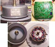
What I thought were photodiodes are just boring old magnetic pickups - not Hall sensors though.
I've been analysing this thing's behaviour, and traced out the circuit - the component number are my own invention - none are marked on the PCB. Very similar - but not identical - to yours Sek.
The bulk of an 'almost SP10 control system' is inside this IC, in a simplified form.
The same principles of operation apply, so we can improve its performance.
There is no push-pull drive on the motor coils - they are switched 'on' only with current in a single direction. I'm not sure I'd bother to change that.
The torque isn't particularly high: the normal operating current is around 60mA, yet the startup current is around 250mA, indicating that when running normally, the system has quite a good current headroom.
Trying to get more current through the motor might damage the IC, and wouldn't improve the torque substantially for reasonable currents.
Beefing up C25/26/27 might be advantageous though.
There is no PLL, but this is not a terribly difficult thing to add.
Poking at pins on the IC, it can be provoked to run the motor a low as 16 rpm, and it will also go up to beyond 78 rpm. Current consumption is only marginally higher - at around 68mA.
So it can easily be converted to a 4 speed turntable - which I will certainly be doing.
Adding a Quartz PLL is not hard either. There is no FG winding, but the platter is already machined with 4 strobe tracks, 33 & 45 rpm for 50Hz and 60Hz.
Any one of these can be watched with a LED/photodiode combination, to derive a tacho signal.
If only 33 and 45 rpm are to be PLL locked, the tacho signal can be read by two opto-pickups (one for 33,one for 45) which means no divider switching is necessary - and a easy crystal frequency like 4.000MHz can be used.
Otherwise a single opto-pickup is fine, but the divider ratios become rather inconvenient. Still, if a microprocessor is being used, the 'nasty' divider ratios are much easier to cope with.
Once a useful phase error signal has been derived, it can be injected into the junction of R4 and R5, adding it to the velocity error signal.
More to follow!
Attachments
How do I have to imagine phase sense coils on the PCB? Can you take a picture of these? I'm asking because that's a true difference to the SL-2000.
A true phase sense would be a great thing to have, as a PLL could reference this to a clock. That's also pretty much how the MK2 series does it; split the tacho signal into magnitude and phase, then inject both of them into separate loops (using integration and differentiation), then recombine the resulting signals into a single error voltage and feed that into the drive IC's error amplifier.
On another note, the drive currents in a SL-1200MK2 motor are 100mA to 180mA continuous (load dependent) and 600mA maximum. Just for comparison.")
Cheers,
Sebastian.
A true phase sense would be a great thing to have, as a PLL could reference this to a clock. That's also pretty much how the MK2 series does it; split the tacho signal into magnitude and phase, then inject both of them into separate loops (using integration and differentiation), then recombine the resulting signals into a single error voltage and feed that into the drive IC's error amplifier.
On another note, the drive currents in a SL-1200MK2 motor are 100mA to 180mA continuous (load dependent) and 600mA maximum. Just for comparison.
Cheers,
Sebastian.
A true phase sense would be a great thing to have,
It would have to be done by means of an added tacho stripe. The resolution inherent in my motor and the early SL1200 is too low - its about 20 pulses per rev I think. Machines like the SP10 have a tacho resolution of 190 pulses per rev.
I'll get a photo of mine. Its esentially just a pcb mounted module with 3 sensors aligned in an arc, about 5mm apart.
This is an extra sensor, not part of the motor itself.
On your circuit, the pink wire of J4, can you see what that does to? I'm guessing it might be a speed sensor.
drive currents in a SL-1200MK2 motor are 100mA
Do you know the voltage?
On your circuit, the pink wire of J4, can you see what that does to? I'm guessing it might be a speed sensor.
Now you made me think!
Take another look at the picture I attached in the first post. You see three pairs of pickup coils arranged 120 degree apart. Additionally, there are three diodes in the upper right mounting area (note that this PCB is not the control PCB, just the one that mounts the coils).
It is easily possible that the pairs of pickups are an arrangement of what you call velocity sense and phase sense coils, respectively. This would then result in a control circuit frighteningly similar to yours.
Please also note that some things in my schematic drawup from back then shouldn't be taken too seriously, particularly the connections labeled with a question mark and the orientation of polarized components like diodes and capacitors.
Do you know the voltage?
4Vpp (peak to peak) as per the service manual, with about 11Vdc bias. I haven't measured it under load, though. Do you have the MK2 service manual handy?
It would have to be done by means of an added tacho stripe.
The voltage derived from the three detector coils (i.e. your L1 through L3) is rectified (i.e. by your D1 through D3) and filtered (i.e. by your R1 and C?), thus injecting a DC voltage into the AN620's pin 15 (pitch).
One idea is to replace this whole arrangement by a quartz referenced tacho stripe DC error signal, just as you noted (PLL injection point) in your schematic.
Building (or reusing) a tacho stripe isn't too difficult, I would expect. The MK2 drive unit has it arranged on the outer side of the rotor's permanent magnet. It gets filtered and amplified to a level of about 0.6Vpp by a simple bipolar transistor circuit and delivers a sinusoidal signal with a period of 20ms for 33rpm, 15ms for 45rpm. Inside the MK2's AN6680 control IC, this signal is then fed to an arrangement of a (presumably integrating/differentiating) amplifier buffer and Schmidt trigger.
Cheers,
Sebastian.
- Status
- This old topic is closed. If you want to reopen this topic, contact a moderator using the "Report Post" button.
- Home
- Source & Line
- Analogue Source
- Improving a turntable (motor controller circuit) ;)