Well, Ca goes from Ra to ground, but not in your schematic.
Mona
Then the modification would be like this, as attached.
Or still it is not correct?
Attachments

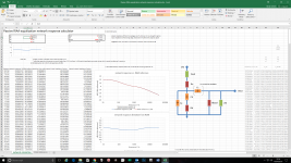
The mod's i sugested where intended to get more headroom and output drive to prevent signal top cutting with strong signals, not to change the frequency response.
The correction network was ok.
What you do now is another way of making the filter, if well dimensioned, same result.
The Rout from the first stage is somewhat less than the 6k8 anode resistor, take 6k.
The Rin is the grid resistor of the next stage, 1M.
Resulting , with the same capacitors Ca=10n and Cb=100n, in Ra=67k and Rb=10k5.
Mona
From here, I thought this is what you wanted to tell me
And is it valid?
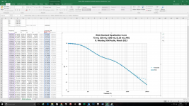
As the time constants are wrong, ms instead of μs, this question is difficult to answer.
Your calculator seems to not take into account stray capacitances, so use it as an approximation, and then run an LTSpice simulation, depending on mathematical models accuracy, it should be more precise.
Last edited:
You are right, my mistakeFrom here, I thought this is what you wanted to tell me

Only excuse is the time, was allmost midnight overhere

Cb has to be 30nF.
Mona
You are right, my mistake
Only excuse is the time, was allmost midnight overhere
Cb has to be 30nF.
Mona
I will install the new component and inform you of the results.
I will install the new component and inform you of the results.
Attachments
Why did you change Zout from 6k to 54k ? It is 6k not 54k !
Mona
Maybe to compensate Zin=Rload=1M ?
Needless to say that input capacitance of next stage will ruin all those predictions...
Old values: Ra=75K, Rb=10k5, Ca=10nF, Cb=30nF, Cc=22n, Zout=6K Zin=∞, Rload=1M, give a decent result if taken into account Cin of next stage.
Last edited:
Maybe to compensate Zin=Rload=1M ?
Needless to say that input capacitance of next stage will ruin all those predictions...
Old values: Ra=75K, Rb=10k5, Ca=10nF, Cb=30nF, Cc=22n, Zout=6K Zin=∞, Rload=1M, give a decent result if taken into account Cin of next stage.
Thanks Popilin for your help, those values are not the old ones but the new ones calculated with the help of our friend Ketje.
The old ones are: Ra 91K, Rb 7K87, Ca 7.5nf and Cb 7.5nf. The values of the capacitors, being parallel / serial the value of Ca and Cb are the same, as you can observe the original circuit differs to the spreadsheet by the arrangement of such components including the resistor Rb.
Attachments
As Kevin pointed out, the 12AX7 in SRPP has an output impedance of about 12K bypassed, unbypassed it is about 30K (!), so the OP should think in another valve or add another stage, e.g. a cathode follower.
Thanks again Popilin for your help, and also KevinKr.
Excuse my ignorance, but I do not know what CPSR means, I would be very grateful if you explain it to me.
Right now keeping the original configuration at the output of the 12AX7 I have a resistance of 59.40K at rest. Again I do not know what OP means.
At this point the phono preamplifier is poorly designed from the beginning?
Why did you change Zout from 6k to 54k ? It is 6k not 54k !
Mona
Sorry Ketje are 6K, 54K that are testing different curves of the RIAA
Thanks Popilin for your help, those values are not the old ones but the new ones calculated with the help of our friend Ketje.
The old ones are: Ra 91K, Rb 7K87, Ca 7.5nf and Cb 7.5nf. The values of the capacitors, being parallel / serial the value of Ca and Cb are the same, as you can observe the original circuit differs to the spreadsheet by the arrangement of such components including the resistor Rb.
OK, just keep the results of post#31, they will work.
Thanks again Popilin for your help, and also KevinKr.
Excuse my ignorance, but I do not know what CPSR means, I would be very grateful if you explain it to me.
Right now keeping the original configuration at the output of the 12AX7 I have a resistance of 59.40K at rest. Again I do not know what OP means.
At this point the phono preamplifier is poorly designed from the beginning?
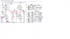
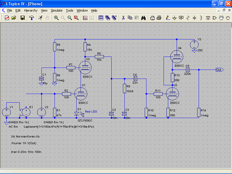
Your circuit is very good, I like it, a cascode as input stage and an SRPP (Shunt Reguated Push Pull) as output stage, just choose another valve for the latter, the 6922 should do the work quite nicely, if gain is not enough just changing Zout and Ra such that Zout+Ra=constant the problem should be solved.
I have no LTSpice model for the 6C45P (adequate here due to its high transconductance), so please obtain the model (maybe opening another thread) and I will run an LTSpice simulation for you to optimize the circuit.
I hope Ketje do not care.
Anyway corrections and critiques will be welcome.SRPP is almost foolproof, so it will work with most resistor values, on condition that not exceed valve limits, of course there are some tricks to make it sing better.
Salas shunt regulator is amazing, so you can build a very good phono preamp.
Edit: Your new circuit is wrong, see capacitors Ca, Cb conection.
Last edited:
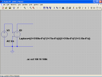
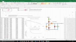
As said before, I do not have LTSpice models for the valves which you want to use, so I used the E88CC/6922
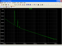
THD is about 0.18%, mostly 2nd harmonic

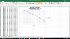
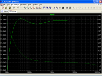
Frequency response is reasonably flat, about ±0.2dB from 20Hz to 20KHz
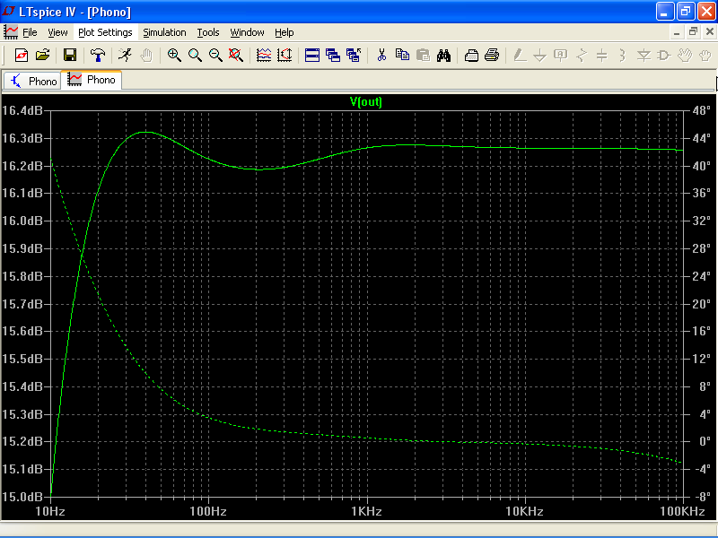
Note that I did use the Laplace transform without the missing time constant 3.18µs as you did so far because the circuit does not allow for it.
THD is about 0.18%, mostly 2nd harmonic
Frequency response is reasonably flat, about ±0.2dB from 20Hz to 20KHz
Note that I did use the Laplace transform without the missing time constant 3.18µs as you did so far because the circuit does not allow for it.
Attachments
- Status
- This old topic is closed. If you want to reopen this topic, contact a moderator using the "Report Post" button.
- Home
- Amplifiers
- Tubes / Valves
- Improvements in this riaa tube