Improved 317
Hi guys,
I'd like to comment on several posts above. There is no question (at least in my mind) that when you move from the Sulzer to the Jung/Didden to the version with preregulators that each step improves the design measurable. And yes, each step brings its own problems and idosynchrasies. But that's how it is. The 317 is cheap, simple, compact. You can only improve by successively attacking the remaining issues: decrease noise output, increase line rejection etc. Each add complexity and cost. Remote sensing adds complexity and can cause instability if not used correctly. On the other hand, it gives you the high performance of the regulator exactly where you need it: at the chip pin! As my friend Jack Cunniff used to say: "Mother Nature is willing to trade, but she never gives anything for free".
But at any given stage you can optimize, and I cannot overemphasise the importance of layout. If you have a 1/4inch of PCB track shared between the load current and the reference return, you degrade the performance significantly and no amount of parts replacement, pre regulators or religious activity can make up for it.
No guts, no glory!
Cheers, Jan Didden
PS If you're serious about this, do invest in the back copies (4) of Audio Amateur on the supply series. Don't forget there was a third person involved, Gary Galo. He actually did the last step: puttting these regulators to work in his amps and reporting on results. All in all 4 articles. You can get them from www.audioxpress.com.
Jung/Didden Regs
I'd love to get a GOOD copy of the PCB artwork, as the ones in my photocopied article are not good enough to produce artwork for making my own PCB from
I've had no problem doing double sided boards WITH traces on both sides, using transparencies taped together, and the unexposed board sandwiched in between and taped to the artwork. It worked great.
The Didden/Jung board specifically does not have a full ground plane underneath, see the articles for the explanation. Still, it's possible to do this, if only someone would supply the artwork, Jan??
Cheers,
RonS
Jung/Didden Regs
>I'd love to get a GOOD copy of the PCB artwork, as the ones in my photocopied article are not good enough to produce artwork for making my own PCB from
Well, they couldn't be. The original articles did not include a pcb design, and you could only guess what they were like from the photo of the parts placement.
To me it was quite a odd behaviour for a magazine read by DIY people.
>I've had no problem doing double sided boards WITH traces on both sides, using transparencies taped together, and the unexposed board sandwiched in between and taped to the artwork. It worked great.
I did do that too for the only Jund/Didden boards that I did. Quite a lot of work though and a bit critical. Would have to be changed for the updated version though, if you don't like "mending-ups" as I do.
>The Didden/Jung board specifically does not have a full ground plane underneath, see the articles for the explanation.
There's a full ground on the parts side: that's what you can infer from the magazine boards photo.
>Still, it's possible to do this, if only someone would supply the artwork, Jan??
Waiting in line for it too, at least to understand better how to make quality pcb designs.
Carlos
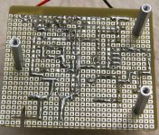
Sorry, the ground plane is on top. The original article did indeed have artwork, but not very good one. Here's a copy of the trace side. I have to look at the original articles again, but there was one layout of the groundplane, but it had component positions on it I think.
RonS
RonS
Attachments
Power supplies for Audio
Audio power supply articles from The Audio Amateur/Audio Electronics/audioXpress
“No-feedback Voltage Regulators,” Andy Nehan, audioXpress 10/01
“Improved Positive/Negative Regulators,” Walt Jung, Audio Electronics 4/00
“ Parallel Regulators For Audio,” Andreas Schubert, The Audio Amateur 4/90
“ Regulators For High-Performance Audio,(4 Parts )” Walt Jung and Jan Didden, The Audio Amateur 95
“A Power Supply Regulator For the Adcom GFA-555,” Kit Ryan, The Audio Amateur4/89
“A Wideband Power Supply,” Jan Didden, The Audio Amateur1/87
“POWER UP: An Overview of Power Supply Considerations,” Richard Marsh, The Audio Amateur3/83
“Measuring Power Supply Impedance (Parts 1 and 2),” James Breakall, et al, The Audio Amateur1/83 and 2/83
“Regulators revisited,” Michael Sulzer, The Audio Amateur1/81
“A High Quality Power Supply Reguator for Op Amp Preamps,” Michael Sulzer, The Audio Amateur2/80
http://www.audioxpress.com/magsdirx/audelex/aabilist.htm
H.H.
Jung/Haller regulator
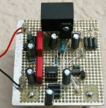
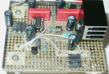
15 volt regulator based on “Improved Positive/Negative Regulators,” Walt Jung, Audio Electronics 4/00 article but with Zetex mosfet buffered Toshiba pass transistor, and improved CCS, and different decopling cap scheme. Built on proto board with top ground plane.
15 volt regulator based on “Improved Positive/Negative Regulators,” Walt Jung, Audio Electronics 4/00 article but with Zetex mosfet buffered Toshiba pass transistor, and improved CCS, and different decopling cap scheme. Built on proto board with top ground plane.
Attachments
Are these protoboards commercially available or have you had them custom made? The pcb factory i normally use will probably have a good laugh if i give them gerber files for those It's certainy tempting though. I wonder if it's posible to manufacture a similar looking board but based on something better than fibreglass. Maybe teflon or ceramics. Would there be a way to glue pieces of copper foil to these materials? I've always had doubts regarding the dielectric properties of fibreglass boards in respect to audio. A few years ago i had this upsetting experience with two presumably identical amps which sounded rather different, and eventually the difference was tracked down to the boards. Well, they did look different in colour (one was a bit yellowish) but the suppliers couldn't shed any light. Since then i prefer glueing the components to a teflon board and doing PTP. Very consistent results.
peter
It's certainy tempting though. I wonder if it's posible to manufacture a similar looking board but based on something better than fibreglass. Maybe teflon or ceramics. Would there be a way to glue pieces of copper foil to these materials? I've always had doubts regarding the dielectric properties of fibreglass boards in respect to audio. A few years ago i had this upsetting experience with two presumably identical amps which sounded rather different, and eventually the difference was tracked down to the boards. Well, they did look different in colour (one was a bit yellowish) but the suppliers couldn't shed any light. Since then i prefer glueing the components to a teflon board and doing PTP. Very consistent results.peter
Teflon
It's a power supply...... low impedances and big caps. I don't think D.A. is a big issue for this type of circuit. 3M makes copper tape that has an adhesive backing. I don't know how well it or anything else sticks to Telfon. I too like to build my critical circuits point to point. DA is really more of an issue with high inpedance circuits which this is definitely not.
"something better than fibreglass"
http://www.trackwise.co.uk/material.htm
analog_sa said:Since then i prefer glueing the components to a teflon board and doing PTP. Very consistent results.
peter
What did you use for glue?
Good question. It doesn't seem to be easy to glue anything to teflon. I just use a glue gun, making sure only insulated cases are in touch with the glue. The joint is reasonably strong for my requirements, but then my projects seldom leave the house. It would be interesting to know what glue can achieve a really strong bond to teflon. Of course the glue gun method allows you to easily reuse and reposition components.
peter
peter

Attachments
- Status
- This old topic is closed. If you want to reopen this topic, contact a moderator using the "Report Post" button.
- Home
- Amplifiers
- Solid State
- Improved LM317 ?