Damping factor
The damping factor is simply defined as the ratio between the load resistance and the amp's output resistance DF = R(load) / R(amp).
So a large amp DF should in theory give a better control of the speaker. However, speaker cone/dome damping is much more complex than that a pure ohmic R(load) and it has been shown that the amp's DF probably contributes less than 1% due to the speaker coils, cabling and xover filters, etc.
But it works great as a marketing fudge factor.
Furthermore, heavy negative feedback reduces the amps output resistance - but then you get into trouble with the people who argue that little or no NF is better.
You also get into trouble with valve (tube) amp affectionados - as these amp's DF are mostly way less than 20.
You just can't win.
I only use a DF when I get a bit too exited, it's called 'a beer and a lie down'
Per, I like your “a beer and lie down” 😊 To expand a bit from yesterday, in the process I got long winded. I’m sorry.
I’ve decided to shop for a 990 or 991 to replace the CC’s 985. I have an unmodded, good, working 981 to get a taste of 990/1 SQ from my Center. What’s your take on removable power cords? The existing is ~2 feet longer than needed and a heavier (14 Ga) is only ~$8-9 shipped.
I have known & understand what you wrote concerning DF for at least 30 of my 40 years in this fun but sometimes trying hobby. Further I understand, many things being the same, how a more powerful amp can better damp or control cone motion.
The one detail concerning the damping factor I don’t get:
higher speaker impedance = higher damping.
Higher connection resistance = lower damping. They seem contrary. I’ve worked the math*. In my mind it* doesn’t line up w/the principle but I don’t fight it. I embrace it. When I tri-amped my LCR, I took great pains to minimize connection resistance. Bigger wire, 8 & 10 ga to woofers & mids. Bigger binding posts to all.
I have a lot more with which bore you - for another session.
I thank you in advance many times over for reading this far and your long distance coaching to “Paulus” my gear.
Tony
I only use a DF when I get a bit too exited, it's called 'a beer and a lie down'
you're so hilarious Per What’s your take on removable power cords? The existing is ~2 feet longer than needed and a heavier (14 Ga) is only ~$8-9 shipped.
I would call that a waste of money (although I would of course never-ever say that in public - it could just provoke the wrath of the oxygen-free reverse braided mains cord crowd
 ).
).The one detail concerning the damping factor I don’t get:
higher speaker impedance = higher damping.
Higher connection resistance = lower damping. They seem contrary.
The speaker drivers can't see whether the amp's output resistance stems from the power trannies, emitter resistors, output coils, protection relays - or the length and gauge of the speaker leads and quality of connections and xover design. So, if the (nominal) speaker impedance is 8 ohms, the interface, say, 0.4 ohms and the direct amp output R is 0.04 ohms, the marketing guys would immediately write the DF down as 8/0.04 = 200, whereas the driver actually sees it as 8/0.44 = 18.
How long is a string of DF?

Per
A thought experiment
Here is a thought experiment about the damping factor.
Think about the most simplified amplifier and loudspeaker system:
There is an amplifier, a short cable or wire and one electrodynamic speaker driver. No passive filters or other components in the circuit.
The cable between the amplifier and speaker is such a short piece of wire that we could easily forget the parasitic properties of it, but let's say there is a tiny resistance RWIRE.
The amplifier is a voltage source VSOURCE capable of producing arbitrary voltage signals. There is also the output impedance of the amplifier, and we may think about it as a resistance RSOURCE.
There is also the speaker driver, which is kind of an electrodynamic linear motor. The voice coil interacts with the magnetic flux and produces force that is pretty much linearly dependent of the electric current going through the voice coil. The speaker driver is a combination of complex frequency-dependent load ZLOAD and a series resistance RLOAD.
All the mentioned components are series connected. We could shuffle their order any way we wish if they stay series connected. Because there are three resistances in the same circuit series connected, we may replace them all with one combined resistance RTOTAL = RWIRE + RSOURCE + RLOAD.
So, what is the damping factor?
What if we could effectively nullify all resistances (with high temperature superconductors or what ever), so that there would be only VSOURCE and ZLOAD chatting with each other, would that be perfect?
Last edited:
Interesting thoughts, Nikolas.
"So, what is the damping factor?"
The DF is a concept/idea that I believe was coined in the 1940'ies - and effectively dissected and dismissed in the 1950'ies as being almost meaningless due to the factors I mentioned above.
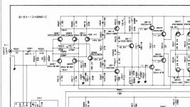
But it hasn't stopped the marketing appetite for more and more fantastic brochure DF spec numbers. Take the Rotel RB-980BX' claim of a DF of 1000. This means that the total output resistance of the output stage, leads, solder joints, speaker contacts, etc. would be 0.008 ohm.
Now, it is true that the 980BX output is brutally direct coupled to the speakers - no fuses, output coils, protection relays, etc. (Save your prayers for your expensive woofers if anything should go awry in the amp).
It also has a (18k2/562 +1) = 33 amplification factor, triple output transistors - but it uses 0.22 ohm emitter resistors. So the open loop output resistance would be at least 0.22/3 = 0.073 ohm. The NFB will (if we assume all components and connections from the VAS stage forward are all perfect zero resistances) reduce that to 0.073/33 = 0.0022 ohm (at low frequencies). Which leaves less than 0.006 ohms for pcb tracks, soldered busbars and jumpers and output connectors. Which may be possible - but then you attach speaker cables with a resistance of 0.1 ohm or more in series. So, what is the point?
"What if we could effectively nullify all resistances (with high temperature superconductors or what ever), so that there would be only VSOURCE and ZLOAD chatting with each other, would that be perfect?"
Yes, that would be perfect - although maybe not perfectly doable. Most "high temp" superconductors still require significant cooling below room temperature. Anyone fancy maintaining a bath of liquid Nitrogen in the living room?
Mind you - it would give you an ice cold can of beer in a few seconds! Hmmm, perhaps worth considering?
"So, what is the damping factor?"
The DF is a concept/idea that I believe was coined in the 1940'ies - and effectively dissected and dismissed in the 1950'ies as being almost meaningless due to the factors I mentioned above.
But it hasn't stopped the marketing appetite for more and more fantastic brochure DF spec numbers. Take the Rotel RB-980BX' claim of a DF of 1000. This means that the total output resistance of the output stage, leads, solder joints, speaker contacts, etc. would be 0.008 ohm.
Now, it is true that the 980BX output is brutally direct coupled to the speakers - no fuses, output coils, protection relays, etc. (Save your prayers for your expensive woofers if anything should go awry in the amp).
It also has a (18k2/562 +1) = 33 amplification factor, triple output transistors - but it uses 0.22 ohm emitter resistors. So the open loop output resistance would be at least 0.22/3 = 0.073 ohm. The NFB will (if we assume all components and connections from the VAS stage forward are all perfect zero resistances) reduce that to 0.073/33 = 0.0022 ohm (at low frequencies). Which leaves less than 0.006 ohms for pcb tracks, soldered busbars and jumpers and output connectors. Which may be possible - but then you attach speaker cables with a resistance of 0.1 ohm or more in series. So, what is the point?
"What if we could effectively nullify all resistances (with high temperature superconductors or what ever), so that there would be only VSOURCE and ZLOAD chatting with each other, would that be perfect?"
Yes, that would be perfect - although maybe not perfectly doable. Most "high temp" superconductors still require significant cooling below room temperature. Anyone fancy maintaining a bath of liquid Nitrogen in the living room?
Mind you - it would give you an ice cold can of beer in a few seconds! Hmmm, perhaps worth considering?
The resistance of the first series inductor in the woofer xover normally swamps most things upstream, save for odd systems; current source amps, very long speaker cables, zero feedback tube, etc..How long is a string of DF?
Per
I’m so grateful all of you opened your hearts to help me understand Damping factor.
From your replies I gleaned:
Rotel RB 980BX has a 1000 DF.
Using 8 ga wire - .0006282 Ohms/ft. 7 ft run to connect directly to the driver
.0006282 X 14* = .0087948 assuming ZERO resistance thru the soldered binding posts and at the driver. *includes add’l 12” of internal 8 ga
Assuming ZERO resistance to the 980’s binding posts,
DF of 1000 8 ohms = .008
.0087948 + .008 = .0167948
8/.0167948 nets an actual DF of 476.XXX...
I could live w/that as the above “example configuration” exactly lines up perfectly w/my reality. I recall from one expert test review a comment to the effect: “we believe the 1000 DF to be close if not true...” though I can’t recall why. If I find the article I’ll post a link.
I wonder if the RB-991 w/its higher power but lower DF (500) could, in actual use DF math aside, match the 980’s damping performance remains to be seen/heard. I doubt I’d replace my 980s w/990s (DF also 1000) or 991s as I’m confident they loaf* even during some the outrageous extended peaks viewing some movies.
* would a fast volt meter tell the tale or for another day?
When I get to it*, I plan to start w/a “Per/Paulus-ed” (tweaked) 991 for my center. As time permits for my retired butt*, I’ll tweak a 981. Then during an extended 2 channel session, I’ll switch around amps to listen/compare a tweaked 981 to a tweaked 991 connected to the various drivers and report to you dudes.
*my would-be workspace not ready and the honey-doo list is... well you know.
1,000 thanks for your indulgence, gents. Tony
I forgot to mention: My chief reason for passing on tweaking the 985 - internals of 5 channels are shoe horned into a case the same size a 980/981. Also while the 980/981/985/990/991 all use the same finals,
980/981 - 6
900/991 - 10
each of the 985’s channels has just 4, and the topography is the most different of the bunch.
980/981 - 6
900/991 - 10
each of the 985’s channels has just 4, and the topography is the most different of the bunch.
I’m very sorry I missed your “snubber“ question from March 3rd, 2020 post 400. I’m “down” for snubber caps. I fully understand their purpose. Hafler uses snubber caps across the rectifier bridges in their XL-280. Why amps at these price points don’t come w/them I don’t get as its just one or two small caps, but what do I know.Hi there Tony,
Thanks for the kudos but i only did the physical work so to speak, the real technical stuff came from Per, I owe him a beautiful sounding pair of Rotel amps.
As i said before, i'm not afraid to tear equipment down and rebuild it but replacing parts for different values let alone design circuitry is very much out of my league
But if you have questions, i'll be happy to answer them to the best of my ability.
Quote:
that requires a set of snubbing caps to slow down and reduce the diode switching noise.
I agree Per
I read somewhere that you don't need to mount them on every diode because the ringing happens in the secondary of the transformer, so use one snubber on the secondary. Does this make sense to you?
Cheers, Paulus
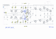
If I had not made it clear, I’m kinda on your level - I need coaching or direction (Schematic changes) to do some of this stuff. I’m good w/soldering iron and can hold my own reading a schematic. But recognizing a CCS, CAS, or a VAS - all alphabet soup to me. I look at these schematics, left to right, I see 4 columns of transistors, a single, then 2 more columns and either 3 columns or 5 columns of finals depending upon the amp.
To Per: having trouble reading your 980 mods schematic, printed or on an iPad w/hi-Rez screen blown up. Any reprint suggestions would help.
Thanks Paulus. As I said before I will follow your lead as best I can using any of your ideas I can make fit - like replacing the 4 PS caps w/8 or more
(I know well the benefit of “more”) while striving for more filtering along the way. Many thanks to you, Per et al
Hi there Tony,
Snubbers; i kinda also understand what they do but i haven't gotten around this subject because there are more (2) ways to tackle the subject....
Every diode in the rectifier is paralleled with a resistor and a cap, the other method is one cap across the secondary winding of the transformer if i'm correct.
Snubbers need to be calculated and i'm not into these calculations
Therefore i do not have any snubbers yet but i'm hoping to get them with the help of someone who understands this.
Then the subject of replacing the psu caps to 8 pieces instead of the original 4. The caps i bought where 10.000 uF instead of the 15.000 uF. Although i was told that the lower capacitance wouldn't hurt at all i thought that if 5000 uF less wouldn't hurt then 5000 uF more wouldn't hurt also.
The new ones are a lot smaller hence there was room for this simple improvement.
That said, there is still room for improving the RB-991......i'm hoping that Per will succeed in developing "current mirrors" for the VAS. The challenge is to develop these with the high voltage used on these amp's.
Cheers
Snubbers; i kinda also understand what they do but i haven't gotten around this subject because there are more (2) ways to tackle the subject....
Every diode in the rectifier is paralleled with a resistor and a cap, the other method is one cap across the secondary winding of the transformer if i'm correct.
Snubbers need to be calculated and i'm not into these calculations
Therefore i do not have any snubbers yet but i'm hoping to get them with the help of someone who understands this.
Then the subject of replacing the psu caps to 8 pieces instead of the original 4. The caps i bought where 10.000 uF instead of the 15.000 uF. Although i was told that the lower capacitance wouldn't hurt at all i thought that if 5000 uF less wouldn't hurt then 5000 uF more wouldn't hurt also
.The new ones are a lot smaller hence there was room for this simple improvement.
That said, there is still room for improving the RB-991......i'm hoping that Per will succeed in developing "current mirrors" for the VAS. The challenge is to develop these with the high voltage used on these amp's.
Cheers
Hi Per,
Trying to find words to describe my perception of the sound before (as i remeber) and the sound now, i just can think of muffled vs open and clear. It's amazing how clear it is now.
The last vinyl i had listen (last June/July) was Janis & Kozmic Blues Band / Live in Amsterdam (recent vinyl press) and i was a bit disappointed with the dull sound, the lack of bass and dynamics. So i thought it could be because of the old (1969/1970) masters quality.
Well, now it seems to be from a different vinyl pressing. It's all there, smooth and round bass, expanded sound dynamics and clear voices as Janis deserves. All sound great.
And my 80's mixtapes now sound better than ever, just as I had a new tape deck.
With more time I will test more CDs and digital music files. I may have to start looking for a USB sound card with a good DAC.
Thank you the improved sound of my return to the past, to the 70's, the 80's, the 90's... the joy of music.
Rui
Hi. Can i ask about mods for a rotel ra04. Any help would be great I have replaced caps and resistors but the input caps are 10uf then 100uf from opamp to switch then 10uf into amp. I tried a 10uf in place of 100uf but the sound was harsh. Is it possible to get rid of this cap safely. Thanks
Hi there Tony,
Snubbers; i kinda also understand what they do but i haven't gotten around this subject because there are more (2) ways to tackle the subject....
Every diode in the rectifier is paralleled with a resistor and a cap, the other method is one cap across the secondary winding of the transformer if i'm correct.
Snubbers need to be calculated and i'm not into these calculations
Therefore i do not have any snubbers yet but i'm hoping to get them with the help of someone who understands this.
Then the subject of replacing the psu caps to 8 pieces instead of the original 4. The caps i bought where 10.000 uF instead of the 15.000 uF. Although i was told that the lower capacitance wouldn't hurt at all i thought that if 5000 uF less wouldn't hurt then 5000 uF more wouldn't hurt also
The new ones are a lot smaller hence there was room for this simple improvement.
That said, there is still room for improving the RB-991......i'm hoping that Per will succeed in developing "current mirrors" for the VAS. The challenge is to develop these with the high voltage used on these amp's.
Cheers
Look for the thread on the Quasizmoto snubber test fixture to understand what they are and how they work.
Also search and read the various viewpoints on diode speed and caps. It does not seem to be a settled argument.
There does seem to be a point where the improvements mean you are using the transformer and case.
Hi ! sorry if i jump in with a too generic and maybe even philosophical question.
I wonder if optimize/improve a low power amp design (i.e. with lower parts count) could be easier than doing the same thing on a more powerful/complex design.
in a nutshell ... upgrading a design like the 820 can be easier than upgrading a 991 ?
because if the answer is positive i would look more to a change of speakers and get some with a very high efficiency to be driven by the lovely improved 820.
I guess this was the norm in the old days when only tubed and low power amps were available.
In the more recent times with lower efficiency speakers appearing on the market clearly the demand of power has increased significantly.
Thanks a lot again for the very interesting and instructive thread.
Last edited:
Hi Ginetto,
A more powerful amp will definitely give you more headroom and power reserve.
But what level are you normally really listening to music on? If you are trying to rip the paint off the walls, force the neighbors to move away or using the amp as PA for a heavy metal band - you'd better go for a high power digital amp.
You are right about the (now) historical drive for efficient speakers. Horns with Lowther, Fostex, Coral, etc.
I run my own floor standing dual internal horn design Angelhorns which have an efficiency of about 96dB and even the 8W Hiraga can make the house shake and blow the fur off the cat.
So the 50W RA-820 (or RA-931) only ever get their volume dial near or over the 12'o'clock position when nobody else is in the house - and I am safely outside in the garden doing a jolly gavort in the rain.umbrella:This is the UK, remember).
But I also have a pair of 89dB Snell J-II bass reflex speakers which I use as a reference, mainly because I have had them since the early 80'ies and know them so well. An RA-820 still has plenty of power for the Snells - and the Rotel upgrades are very clearly audible.
The main reason that the 991 is more difficult to upgrade is that it is so high rail voltage and has a double differential topology design, whereas the 820 is a more classical single LTP/VAS amp.
Maybe Paulus has other views on this?
Best,
Per
A more powerful amp will definitely give you more headroom and power reserve.
But what level are you normally really listening to music on? If you are trying to rip the paint off the walls, force the neighbors to move away or using the amp as PA for a heavy metal band - you'd better go for a high power digital amp.
You are right about the (now) historical drive for efficient speakers. Horns with Lowther, Fostex, Coral, etc.
I run my own floor standing dual internal horn design Angelhorns which have an efficiency of about 96dB and even the 8W Hiraga can make the house shake and blow the fur off the cat.
So the 50W RA-820 (or RA-931) only ever get their volume dial near or over the 12'o'clock position when nobody else is in the house - and I am safely outside in the garden doing a jolly gavort in the rain.
umbrella:This is the UK, remember).But I also have a pair of 89dB Snell J-II bass reflex speakers which I use as a reference, mainly because I have had them since the early 80'ies and know them so well. An RA-820 still has plenty of power for the Snells - and the Rotel upgrades are very clearly audible.
The main reason that the 991 is more difficult to upgrade is that it is so high rail voltage and has a double differential topology design, whereas the 820 is a more classical single LTP/VAS amp.
Maybe Paulus has other views on this?
Best,
Per
- Home
- Amplifiers
- Solid State
- Improve a Rotel amp THD by 20dB!