Interesting, some questions:
1) You didn't use transformers on the input signal?
2) You didn't add a volume potentiometer?
In my design i try to incorporate a switch in order to choose between XLR and RCA output.
Also if I add a DC panel meter on the second tube, does it mean that slight change to the LEDs has to be done?
1) You didn't use transformers on the input signal?
2) You didn't add a volume potentiometer?
In my design i try to incorporate a switch in order to choose between XLR and RCA output.
Also if I add a DC panel meter on the second tube, does it mean that slight change to the LEDs has to be done?
It looks like that at the moment, but I don't think it's just that chip. There's a global chip shortage at the moment caused by higher demand due to lockdown etc and I think there's been a pretty major fire at one of the chip factories. I thought I had a load spare but I don't seem to be able to find them at the moment.


Am I correct that DN2540N5 are impossible to get? Looked everywhere -- out of stock
DN2535N5 is in stock at Mouser -- 350V, not 400V.
If not happy and stuck, I have 3 tubes of DN2540N5.
You can always just use a resistor -- with a regulated power supply the prodigious impedance of the DMOS ccs may be a bit of overkill.
The pcb worked!
Here is the ImPasse with a Salas input selector and sowter 3575 trans on top of an F4!
The first of the DN2540N5 on every side seems to get too hot, I cannot touch it. The second one seems ok.
Any suggestions here?
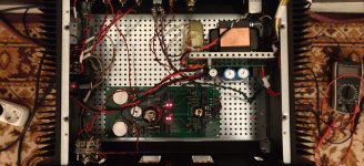
For anyone interested on the PCB I haven't heard from SY so I do not know if it is good to publish it...
Here is the ImPasse with a Salas input selector and sowter 3575 trans on top of an F4!
The first of the DN2540N5 on every side seems to get too hot, I cannot touch it. The second one seems ok.
Any suggestions here?
For anyone interested on the PCB I haven't heard from SY so I do not know if it is good to publish it...
Attachments
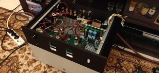
Added the heatsinks and everything seems ok.
I am still puzzling my head how can I add one balance input with the salas selector or maybe a second selector. The goal is to use an arduino to change the the inputs and the volumes with a remote...
The PCBs worked fine with no hiss or buzz or anything! The sound is good.
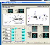
One issue that I cannot understand:
1) I measured the split load phase splitter voltages and found that with 15K for R11 and R12 the voltage drop on the resistors are about 90V and 170V on the tube instead of 120V and 100V as SY has said on his article.
2) I also checked with TubeCAD from glassware and seems that my measurements holds true.
What am I missing here?
I am still puzzling my head how can I add one balance input with the salas selector or maybe a second selector. The goal is to use an arduino to change the the inputs and the volumes with a remote...
The PCBs worked fine with no hiss or buzz or anything! The sound is good.
One issue that I cannot understand:
1) I measured the split load phase splitter voltages and found that with 15K for R11 and R12 the voltage drop on the resistors are about 90V and 170V on the tube instead of 120V and 100V as SY has said on his article.
2) I also checked with TubeCAD from glassware and seems that my measurements holds true.
What am I missing here?
Attachments
Yes I will do that but trying to understand, why is there such a difference? It is tube related?
I reread the thread and found that lehmanhill had the same problem here
(ImPasse Preamplifier)
I reread the thread and found that lehmanhill had the same problem here
(ImPasse Preamplifier)
- Home
- Amplifiers
- Pass Labs
- ImPasse Preamplifier