Looking for a set of boarded to build the pre.
If you don't get a response from other guys or just want to get going, check post #1053.
Jac
In case somebody plans to start Impasse project I am selling my PCBs and power transformer:
Impasse Pre-amplifier PCBs | eBay
Hammond 373AZ Power Transformer | eBay
Impasse Pre-amplifier PCBs | eBay
Hammond 373AZ Power Transformer | eBay
Ah, it would be very nice for my balanced-bridged F4.
Yes, it would be perfect to drive 2 F4s in balanced configuration as Impasse is designed to do exactly that
")
gate and grid stoppers.
Having been reading the his masters noise article Ive noticed that Sy specifies carbon resistors for the gate and grid stoppers.
I (think I) know that grid stoppers are usually carbon comp. To do with being non inductive to avoid oscillations kicking off (miller capacitance?).
Anyway, each time ive been rebuilding the ccs for the impasse ive been using metal films. R5 was specified as metal film but R6 R7 were just specified as 120R.
I can only assume that the instructions regarding ccs for HMN would also apply here. They're doing the same job right?
When "whatever" kicks off from using inductive components, like the grid or gate stoppers, is this likely to be a constant thing or could it start and stop based on changes elsewhere in the circuits? Its made it unstable rather than broken the circuit?
I just wonder because every time i rebuild the ccs my symptoms do alter, whether its more in the left or right hand channel, and im sure ive not fried the dn2504 this time with static. Repowering the preamp can often help.(have you tried turning it off and on again!)
The main difference each time being the configuration of resistors i use to make R5 to set the current. Im wondering if that, or more likely the difference in value of R5 is interacting with R6 and R7. This would explain the similar yet different balance of noises each time.
Does any of that make sense or am i spouting nonsense?
Thanks
Having been reading the his masters noise article Ive noticed that Sy specifies carbon resistors for the gate and grid stoppers.
I (think I) know that grid stoppers are usually carbon comp. To do with being non inductive to avoid oscillations kicking off (miller capacitance?).
I can't find it, but I recall reading someone asking SY about using carbon composite resistors, probably for grid stoppers. SY's reply, if I remember correctly, was that he did it as a tradition, but didn't feel it was very important.
I would assume that your noise isn't very high frequency (at least compared to RF) since it is changing in the audible range. I know that the military uses special resistors for high frequency, low noise applications, for example, Vishay ERL (RLR military), but then I think they are for MHz and GHz kinds of frequency.
Jac
Hi mrdave45,
Carbon composition resistors are used because they aren't inductive at high frequencies. Their use in warranted in this application to avoid instability. Inductance in gate or grid leads can allow the component to oscillate, or to ring. Stuart chose wisely in this instance.
From here forward, I would encourage you to use the carbon composition resistors for these applications. They are used often in high frequency (radio) equipment for those same reasons. Remember, the circuit may not have a very high frequency response, but I can assure you that individual parts will operate happily at several MHz - all on their own.
-Chris
Right, replaced the gate stoppers today. I havent put carbon comps on the grids yet. I already had "completely non magnetic" resistors there. Those red PRP resistors. (please comment on this!)
However, i did notice that the heater wires were coming out the output end of the board just under the left output side. Ive generally had more noises on the left hand channel.
I think also a dodgy phone charger has been agravating the situation intermittantly. I think its somehow been getting past the mains filter. Maybe its showing up on the heater wiring.
Ive tried bringing out the heater wires (tightly twisted) off to the side underneath the board where the HT wires are going in. Ill see if that helps.
Wondered where you guys are bringing the heater wires out. I think if i were to build it again i would try to get the heater wires coming out through the gap in the B9a(?) base and going up vertically to get them away from the board asap.
I also wonder if im getting some rectifier hash showing up.
Has anyone used snubbers on the psu diodes?
I guess that either using a separate heater transformer or even a DC heater supply like the "His masters noise" would be a nice upgrade.
I'm not to that stage yet (close). Please report on your experience with noise and heater/power wiring.
In my case, the Impasse and the F4 (single ended) are in the same box (4U) and I've had to stack the power supply boards above each transformer. That worries me because I read somewhere that noise getting into a circuit is a function of the incident angle between the source and the circuit. In other words, a noise source that is along the edge of the board is less likely to pick up noise than a source that is significantly above or below the board. At least that's my interpretation.
At least I was able to keep the diode bridge on the floor at about the same height as the Impasse signal board. I did use the old style, diode bridge in a block. The type that 6L6 likes, among others. I have put snubber caps between the bridge poles, but I haven't fired up the power supply yet.
I am also reading that twisting wires improves on both noise source and noise reception, so I am trying to twist mains wires and heater wires, in addition to signal wires, at 4 to 6 twists per inch. Since my case has a false floor, my back up plan is to bring the heater wires under the floor and vertically into the bottom of the Impasse.
I look forward to hearing what you learn.
Jac
Hmm, didnt seem to learn much form that exercise.
Ive now tried putting much bigger heatsinks on q2.
Has anyone heatsinked Q1? I dont think theyre really dissipating much so i dont think thats an issue.
Im revisiting grounding.
At the moment i have the input transformer (cinemag cmli15-15) wired so the primary faraday shield (pin2) is connected to input ground (pin 1). This is not connected to the chassis so the input signal is isolated form the board by the transformer and presumably takes its ground reference from the source.
The can (pin7) is connected to chassis star ground. Rather a long wire in my opinion.
The secondary faraday shield (pin6) is connected to audio ground on the pcb.
The lead for audio ground from the psu to star ground is rather long. Should i move this closer and have longer wires for the other connections to star ground? That would also shorten the tx can wire (pin7) significantly.
Im seeing lots of diagrams connecting faraday shields to audio ground. On a power tx you connect with a very short cable to the chassis locally. Why wouldnt you connect the faraday shields of your input tx to the chassis? This tx has 2 of them.
Output xlr pin 1 is now connected to the chassis.
The impasse is running unbalanced in and then to the F4 single ended off the negative (xlr pin3) output.
And finally (probably most importantly), Im not convinced my chassis has particularly good earthing. The earth bond from safety ground is securely fastened to the base plate (paint scraped off etc) and that part is fine. Is there an easy way to ensure that the different panels are in fact suitably connected electrically as it seems just screwing the thing together as per instruction doesn't seem to be good enough. It doesnt seem right to have to scrap paint off at all the seams or screw holes? The face plate and control knobs/switches all show continuity to safety earth though. Just want to make sure that the rest is properly connected also and not 'hanging on by a thread'.
This ones a painted steel chassis from HIFI 2000. I think ill be getting full aluminium ones from now on as this wasnt an issue on my f4 build.
I've done some tracing on the boards that Jacinnj designed. Maybe that will help.
Jacinnj left several grounds optional with traces that can be connected, but are not connected unless you decide. I have the components on the board, but haven't fired it up yet, so I don't know which grounds are useful for noise. Perhaps Jacinnj or other Impasse builders can comment on where they connected grounds.
I am using Cinemag CMLI-15/15PCA trafos that were supplied with the board. Here are the pin-outs for the Cinemags.
Cinemag pin 1 to XLR pin 3
C pin 2 to XLR pin 1 (optional ?chassis? ground connection)
C pin 3 NC (no connection)
C pin 4 to XLR pin 2
C pin 5 to AGND, bottom of C1, P1 (audio ground of the pcb)
C pin 6 NC (option to AGND)
C pin 7 NC (option ?chassis? ground connection)
C pin 8 In+, top of R1, P1
SY's schematic and the Cinemag datasheet shows pin 6 connected to AGND.
Sy doesn't show any other ground connections to the trafo, but the typical application in the Cinemag datasheet shows both pins 2 and 7 to ground. Is that power system ground? input signal pin 1? chassis ground?
I would be curious to know what ground connections were made on quiet Impasse builds by other builders.
Last edited:
Output xlr pin 1 is now connected to the chassis.
The impasse is running unbalanced in and then to the F4 single ended off the negative (xlr pin3) output.
And finally (probably most importantly), Im not convinced my chassis has particularly good earthing. The earth bond from safety ground is securely fastened to the base plate (paint scraped off etc) and that part is fine. Is there an easy way to ensure that the different panels are in fact suitably connected electrically as it seems just screwing the thing together as per instruction doesn't seem to be good enough. It doesnt seem right to have to scrap paint off at all the seams or screw holes? The face plate and control knobs/switches all show continuity to safety earth though. Just want to make sure that the rest is properly connected also and not 'hanging on by a thread'.
This ones a painted steel chassis from HIFI 2000. I think ill be getting full aluminium ones from now on as this wasnt an issue on my f4 build.
One question comes up. Have you run a ground to the output + (plate side) of the XLR? This was recommended by SY in the article for single ended output.
As for connecting the output XLR pin 1 to chassis ground, I wonder if this couldn't be a noise source. I wonder if you don't need some sort of isolation from the chassis, or completely floating the audio ground? I don't know the answer, just worrying about power supply noise getting in this way.
As for case ground integrity, I usually just go on resistance between screws connecting plates and, where possible, scraped off paint to panels. I've always found screwed together cases to have good continuity, in part because I don't paint inside screw holes.
I actually like steel enclosures. In some ways they are better at shielding than aluminum. And soft steel is trivial to bend if you are making your own. Of course, ally is prettier.
Jac
Last edited:
Thinking about it a bit more and I would explore your pin 1 output to ground, if I were you. Per SY's original schematic, he has a ground breaker circuit between the power supply ground and the chassis ground. Audio ground and power supply ground are connected but isolated from the chassis by the ground breaker and from the input by the Cinemags.
Jacinnj's boards follow this scheme. There is a star ground on the power supply board and on the signal board.
It would be easy to put together a little ground breaker circuit on a separate board.
Good luck.
Jac
Jacinnj's boards follow this scheme. There is a star ground on the power supply board and on the signal board.
It would be easy to put together a little ground breaker circuit on a separate board.
Good luck.
Jac
Hi Jac,
I had only connected the output PIN 1 xlr to chassis a couple of days ago. all this time with the noise troubles the output had been left as you suggested. This is something i am trying having reread the diyaudio grounding article.
I also have the plate output shorted via the xlr connecter on the interconnect as the article suggests.
This is the scheme i originally used to wire the thing up with.

The main difference now is that i have a better line filter. The safety earth is now on its own bolt. I have a dual pole mains switch without the cap. Doesnt seem to be sparking. The power tx now has its shield connected to the chassis right next to it.
That means i can move the star ground right close to the 2 boards and have much shorter wires. Just what to do with the faraday shields on the cinemags. I have the same one as you btw.
I had only connected the output PIN 1 xlr to chassis a couple of days ago. all this time with the noise troubles the output had been left as you suggested. This is something i am trying having reread the diyaudio grounding article.
I also have the plate output shorted via the xlr connecter on the interconnect as the article suggests.
This is the scheme i originally used to wire the thing up with.
The main difference now is that i have a better line filter. The safety earth is now on its own bolt. I have a dual pole mains switch without the cap. Doesnt seem to be sparking. The power tx now has its shield connected to the chassis right next to it.
That means i can move the star ground right close to the 2 boards and have much shorter wires. Just what to do with the faraday shields on the cinemags. I have the same one as you btw.
i am sure SY will not mind, i discussed this with him....
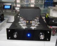
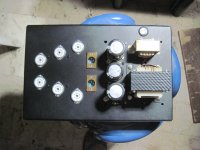
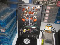
my 5814 long tail pair version of the Impasse..
Very cool!
Very cool!
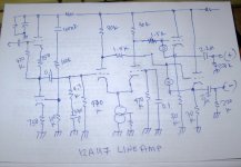
thanks, this is my schematics...B+ is 250 volts
Attachments
- Home
- Amplifiers
- Pass Labs
- ImPasse Preamplifier