Regarding the d MOSFETs, you (sy) mentioned that you had a lot of varience with them and discarded 2/3. Should I be matching those first?
I didn't discard them, I just put them aside for different projects. I am a cheap guy.
 What you want to match for is current with a fixed source resistor. I show how to set that up in the ImPasse article.
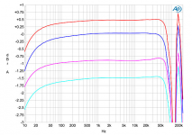
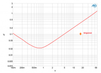
Here's a $19k tube line amplifier ($7k plus for the phono stage) which gets into trouble quickly. I'd suggest that you don't need an SYS2722, just a scope or network analyzer with gain and phase measurement capability out to 1MHz.
Those are the only bricks I am going to throw this morning. Certainly should answer the question of "Why DIY?". One of the advantages of the Impasse is that as the tubes age, the channels are going to "mature" about equally.
Those are the only bricks I am going to throw this morning. Certainly should answer the question of "Why DIY?". One of the advantages of the Impasse is that as the tubes age, the channels are going to "mature" about equally.
Attachments
I should mention that matching is only important if you want to use the same source resistors in both channels. If you don't mind, say, a 200R on one side and a 300R on the other so that you have the same current, that won't change the performance.
I tend to be a bit anal retentive about things like that.
I tend to be a bit anal retentive about things like that.
Since this preamp is specifically designed to work with the Pass F4, I'm taking the liberty of moving the thread to the Pass forum.
Since the Impasse debuted, have you or others implemented any revisions that I should know about?
Are there certain tube suppliers of specific brands of 6SN7 tubes, or better sounding alternatives, that you would recommend for best performance with my speakers, such as http://www.sophiaelectric.com/ ?
Any particular brand for the 6922 tube, or better sounding equivalent?
Have you been pleasantly surprised when “tube rolling” the Impasse, especially when driving the F4?
If you've ever heard the Impasse/F4 combo driving any kind of horn speakers could you describe the sound? Except for my pair of Rythmik 12" sealed subs, my speaker system is a clone of Gary Dahl’s Azurahorn 425/Radian 745 Neo Be/GPA Altec 416 system. http://www.diyaudio.com/forums/multi-way/100392-beyond-ariel-720.html
R5a adjustment resistor.
Right. Finally getting round to sorting out my preamp. Have got the new bits. The rustling I was talking about is still there which I intend to replace the transistors etc.
There is a new intermittent fault which does increase with the volume pot. I have a stepped attenuator to go in place.
When I installed the valve base in the wrong orientation I think it connected the heater supply to the1k grid stopper on one side and to the LEDs on the other so am replacing the LEDs too and I'm wondering if it may have stressed the volume pot.
Anyway. My question is. One of the ways to work out the value of r5a to trim the current to 8ma is to use a trim pot then measure it and find an appropriate resistor. Is there any reason why I shouldn't use the trimmer in situ. I have a 25 turn bourn's 5k trim pot that's rated to 500 mW so should take 35v across it at its mid point before failing. I think the resistor currently there is 2k7 250mW. Or do trim pots drift too much for this application.
Is there any reason why I shouldn't use the trimmer in situ.
Mostly my own worry about long term reliability of potentiometers with current flowing through the wiper.
Sometimes the trimmer wipers are reported to fail with "ever-present" DC, although I haven't seen it happen (the Pass F5 comes to mind -- I have one which has been running for years without a problem.)
I use a 25 turn 10k potentiometer to adjust the parallel value. Then solder in the correct value. Sometimes you get the "Homer Simpson" moment when the paralleled value comes out to be one available in the E48 range.
I use a 25 turn 10k potentiometer to adjust the parallel value. Then solder in the correct value. Sometimes you get the "Homer Simpson" moment when the paralleled value comes out to be one available in the E48 range.
right, been having a good play with the css circuit of a bread board and matched them to 8.00v across my 1k resistor so im confident they are matched.
I replaced the LEDs with 2 different sorts. I couldnt find anything with a drop of 1.7 but did find 1.61 and 1.813 so i matched 2 pairs to give 3.42v. (all red!)
The 12k5 resistors that were with the kit measured 12k and 12k4.
From playing about on the bread board for a given current as R4 is reduced in value the voltage drop across r4 drops and the voltage drop between the drain of q2 and the bottom of r5 increases. Presumably meaning the css (probably q2 specifically) has to disipate more heat.
Wierdly i think it was the side that had the 12k4 resistor was the one that was getting hot.
I had bought a load of 12k (couldnt find 12k5) power resistors in the hope that the 5% tolerance would allow me to find a 12k5 but they all measured about 11k95.
Anyway, as one of the power resistors was 12k already i didnt see much harm in sticking in a matched pair of the new 12ks. Ive powered up and q2 was getting on the warm side (67 degrees) I turned off and added a heatsink to q2 on both sides.
It seems to have stabilized at about 62 degrees. Although Im not entirely sure if thats the actual temp of the transistors. The thermometer is occasionally picking up heat from the tubes. If i take the temp overhead it measures lower and i think the hottest part is near the bottom of the plastic.
Do you think this is probably ok or should i get 500r power resistors to connect in series with the 12k resistors.
something that i really dont get though is my plate voltages are different. Im getting 127.9v on one side and 136v on the other measure between the plate end of R4 and the ground stubb on the pcb. the voltage drop across R4 is 96.6v and 96.7v on the other side. As i matched these resitors to 11k94 i am confident that the CSS is performing well and matched pretty closely to around 8.09mA/8.10ma
Ive been really careful to match all the parts.
Are different plate voltages normal on 2 sides of the 6sn7?
I havent connected the volume control yet.
Thanks
Last edited:
Hey guys, Thanks for your help. I now have it up and working. The stepped attenuator is going to take a little getting used to as the clicks are a bt disconcerting, the tapers different so you end up turning it round further and it also goes round further too!
It does seem to sound better though. Treble has a lot more detail and im getting to the stage where i feel its revealing the quality of source somewhat more ruthlessly! I have an EE dac supreme arriving next week so that should be interesting!
Unfortunately the rustling sound is still coming in every now and then. Im coming to the conclusion that the issue is somewhere else. I have a pair of krk monitors in the study and they have recently been displaying similar behaviour. i did have a problem with a power supply in one (fixed) and I have sort of assumed that as they are now being driven from the built in output from a gigabyte brix PC that it was down to that or that they are over 10 years old and cheap bits were just starting to fail. When they were in my studio they were going through some mains filters although i have been having issues with noise on a mic preamp.
As the impasse has very good noise rejection of the power supply do you think its more likely that my power amp is picking up noise from the mains?
I have been having issues with smps causing all sorts of wierd stuff on the ground. I measured 90v or so AC on the chassis and it was being caused by a MS Kinect psu. I have deplugged this and the sound improved. (and it stopped shocking me!).
Is there anything else i should check with the impasse before changing forums and start trying to improve the mains situation.
On the plus side I have learnt loads through poking about and measuring the circuits on the breadboard.
Thanks Again.
Well, the left channel of my Impasse went out today. The right works fine. The symptom (for me) is very odd. With the volume at zero and the F4 off, I get distorted output and a hum with my (fairly efficient) speakers. Turning the amp on results much louder version of the same, though I only tried this once
I am wondering if a capacitor went or perhaps the stepped attenuator? I was going to start by comparing each node voltage to ground and go from there.
Not too many elements in the circuit at least!
I am wondering if a capacitor went or perhaps the stepped attenuator? I was going to start by comparing each node voltage to ground and go from there.
Not too many elements in the circuit at least!
Hi there.
Tempted to ask what happens if you swap the inputs to the f4 round but if something nasty has happened like failed output cap (unlikely I would think) you would probably damage the other side of the f4 if that's what's already happened. (Not saying it has, but if it has you don't want risk both sides).
I don't think this is the case. I'm sure that if you had whatever the DC offset is before the blocking cap make it in the you f4 something would have gone bang quite spectacularly .
Are you using a single f4 or 2 f4s bridged?
I would start by removing the impasse and with the power off, caps discharged etc poke around with a multimeter for anything obvious. Check that what you measure across the stepped attenuator matches on both sides and that any blocking caps on the output haven't gone open.
If all looks good I would then power up and check the power supplies.
I nearly came a cropper working on mine as I needed to measure the temperature if q2. I only recently fully realised that the HT supply is on the tab of the transistors. Luckily setting in my head said probably best not touch that, just in case!
So if its too loud and distorted it sound like somethings caused the gain to be increased. Maybe the tubes knackered.
But, all in all, if the volumes off and you are getting output that does point to the stepped attenuator. The input to the first valves grid stopper (check this, I'm going on memory!) should be shorted to ground so no signal should be getting through.
I have two F4 in bridged configuration. It's definitely not the amp, because the "good Impasse channel" works with both F4s. I am doubting it's the PSU because if I recall, I have a single B+ for both channels. I do need to confirm that. I did try another set of tubes with the same results. I ended up plugging another piece of gear in its stead for now (interestingly, a Schiit Audio solid-state Circlotron headphone amp, the "Mjolnir" which has a preamp output) and it's working great.
Anyways, the joys of DIY
Anyways, the joys of DIY
- Home
- Amplifiers
- Pass Labs
- ImPasse Preamplifier