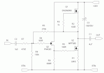
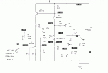
I just fired up my HP8903A for the first time with my breadboard shut away in a diecast bud box, and I'm getting results between .01-.05% distortion depending on frequency and amplitude. I find it somewhat suspicious that using a 1kHz center frequency, I get a really significant reduction in distortion when I engage the 80kHz high pass filter. This points to either pickup or oscillation. I probably need to change the input BNCs to ones isolated from the case, and use a single point ground. It would probably be productive as well to ground the box to one of the front panel ground connectors on the 8903A - which one? At any rate. I'll also be looking at my breadboard with a square wave input to try and smoke out any instability. Things are never really straightfoward....
Last edited:
With the current setup, here's what I get for THD with the 80kHz LPF in place - 1kHz, 0.1V - 0.027%, 1kHz, 0.5V - 0.016% 1kHz, 1V 0.036%
10kHz, 0.1V - 0.03%, 10 kHz, 0.5V, 0.05%, 10 kHz, 1V - 0.154%
Gain is ~ 5.5, so the more realistic level of excitation is 0.1-0.2V.
Obviously, I need to put some more work in the setup. Another useful thing might be to cascode the depeletion mode mosfet current source I'm using for a load in order to cut down on its capacitance - this may improve the 10kHz distortion.
With the current setup, here's what I get for THD with the 80kHz LPF in place - 1kHz, 0.1V - 0.027%, 1kHz, 0.5V - 0.016% 1kHz, 1V 0.036%
10kHz, 0.1V - 0.03%, 10 kHz, 0.5V, 0.05%, 10 kHz, 1V - 0.154%
Gain is ~ 5.5, so the more realistic level of excitation is 0.1-0.2V.
Obviously, I need to put some more work in the setup. Another useful thing might be to cascode the depeletion mode mosfet current source I'm using for a load in order to cut down on its capacitance - this may improve the 10kHz distortion.
Need to also tell us source output impedance (assumed to be 50 ohms) and load input impedance (assumed to be 1M ohm or greater for test gear). Try a load of 1k, 10k, 100k, and see what happens to your numbers.
Tweak the supply voltage , shown as +30V, up and down if possible, and see what happens. This may show a sweet spot. Simulation meets the real world.
The source impedance of the 8903A is 600ohms, with an input impedance of 100K. I won't tinker with these until I am sure of a proper setup. I modified my test box (it already had isolated in/out jacks) for a single point ground to the case, and connected that ground to one of the ground connectors on the 8903A front panel. The resulting measurements were made with 400 Hz LP and 80 kHz HP filters engaged:
1k/0.1V - 0.021%, 1k/0.2V - 0.012% 1k/0.3V - 0.011% 1k/0.4V - 0.0125% 1k/0.5V - 0.015%
10k/0.1V - 0.024%, 10k/0.2V - 0.022%, 10k/0.3V - 0.03%, 10k/0.4% - 0.039%,
10k/0.5V - 0.049%
1k/0.1V - 0.021%, 1k/0.2V - 0.012% 1k/0.3V - 0.011% 1k/0.4V - 0.0125% 1k/0.5V - 0.015%
10k/0.1V - 0.024%, 10k/0.2V - 0.022%, 10k/0.3V - 0.03%, 10k/0.4% - 0.039%,
10k/0.5V - 0.049%
Should have done this a while back. but here are the residuals read on the 8903A with a BNC cable hooked from in to out. I'm not all that impressed - maybe this beast needs a cal session, fresh caps, or a better cable (the ones I have feel dodgy). Anyway, with 400 Hz LP and 80 kHz HP engaged, the results are:
1kHz: 0.1V/0.0081% 0.2V/0.005% 0.3V/0.0047% 0.4V/0.0048% 0.5V/0.005%
10kHz: 0.1V/0.008% 0.2V/0.0047% 0.3V/0.0041% 0.4V/0.0043% 0.5V/0.0045%
Can some one else that also has an 8903A comment on these residuals?
1kHz: 0.1V/0.0081% 0.2V/0.005% 0.3V/0.0047% 0.4V/0.0048% 0.5V/0.005%
10kHz: 0.1V/0.008% 0.2V/0.0047% 0.3V/0.0041% 0.4V/0.0043% 0.5V/0.0045%
Can some one else that also has an 8903A comment on these residuals?
the spec on the 8903A in the range you are using is -80dB, or .01%
manual here - see page 1-13
http://www.ece.stevens-tech.edu/BoeschLab/Man-AudioInstrum/HP8503-AudioAnalyzer/UsersManual.pdf
also comments here
http://www.diyaudio.com/forums/equipment-tools/168385-differences-between-hp-8903a-hp-8903b.html
Looks like yours is OK. Maybe try an FFT method, like ARTA on a PC soundcard? That way you can see the harmonics.
OK, so the 8903A is operating near (actually below) its published limits, and there's not a lot of difference between the 1kHz and 10kHz residuals (though the rise at low amplitude is a bit troubling). Anyway, it's established that the 10kHz THD is definitely higher than the 1kHz THD for the basic version of the "FETSchade" as shown.
The circuit depends on high levels of very local feedback for low THD, so that anything that impacts the open loop gain should affect the THD. There are two things that I can think of. The first is that any real current source load will have a finite impedance (albeit high) associated with a shunt capacitance. A single DN2540N5 has ~1M impedance (dependent on bias current?) with some associated shunt capacitance that will result in reduced open loop gain as a function of frequency. Also, the gain mosfet still has Miller capacitance, even though said capacitance is being driven with a source follower.
So, there are three approaches to reducing the 10kHz THD. The first would be to increase the gain mosfet transconductance by boosting the bias current, hoping that the impedance of the depletion mode current source load is not too adversely affected by the increased current. The second approach would be to cascode the current source load somehow. The third approach would be to cascode the gain mosfet. The fourth approach would be to accept the increased distortion and forge ahead.
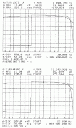
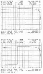
Anyway, I finally got a chance to drag my test setup in to work and do a gain-phase plot on a HP 4194A gain-phase analyzer (if I ever hang out a shingle as a consultant, I want one). The frequency response is not shabby at all. The first attachment shows the G-P plot with markers at 1 kHz and 10 kHz.
Attachments
While you are at it, what about a current source under the JFet input buffer?
Have you tested the stages individually? That could be a weak link. We know that the B1 implementation, for instance, or similar BF862 versions, both using 2 JFets, one as current source, the other as buffer, have extremely low distortion, i.e. ballpark under -100dB.
Have you tested the stages individually? That could be a weak link. We know that the B1 implementation, for instance, or similar BF862 versions, both using 2 JFets, one as current source, the other as buffer, have extremely low distortion, i.e. ballpark under -100dB.
The first incremental change I applied to the circuit (actually a double change) was to add a cascode fet to the CCS drain load. The circuit now uses a DN2530N3 (TO-92) depletion mode fet for the current source and the original DN2540N5 (TO-220) depletion mode fet for the cascode. While I was at it, I reduced the current-determining resistor on the bottom device of the cascode to 61R9 from 100 ohms. This raised the bias current from ~20 ma to ~30 ma. The increase in the bias current improved the output centering.
The changes were beneficial, as evidenced for the distortion readings:
1kHz/0.1V - .014%, 1kHz/0.2V - 0.007%, 1kHz/0.3V - 0.005%, 1kHz, 0.4V - 0.0047%, 1kHz, 0.5V - 0.0047%
These numbers hug the residual readings of the analyzer for the most part.
10kHz/0.1V - 0.0153%, 10kHz/0.2V - 0.0143%, 10kHz, 0.3V - 0.0193%, 10kHz/0.4V - 0.0262%, 10kHz/0.5V, 0.033%
These numbers are an improvement over the earlier measurements.
While I was at it, I hung a probe on the output of the circuit with no input and detected a snarky little oscillation at a couple of MHz. This may be the reason why engaging the 80kHz low pass filter cleans up the distortion readings so much.
My next step will be to drag the thing off to work for a little square wave excitation and compensation work.
Why don't you try this yourself?
Ok, I will when I have time.
My bench is overcrowded with another active project, and 2 waiting in the wings. And both bosses (the one at work, and my wife) just handed me more things to do, due yesterday.

Best wishes on the project.
I dragged the "fake SIT" in to work today for some square wave testing, which revealed some overshoot plus ringing at the edges - not too bad, but I don't like to see any. I put together a "gimmick" using some tightly twisted 26 AWG Tefzel wire (~3pF) and placed it across the 274k gain resistor. This changed my square wave response to overdamped, but a bit slow, so I lopped about !" off the gimmick. This sped up the output rise time to ~1usec, still overdamped. Declare victory!  While I was at it, I added 10 nF bypass caps from return to chassis at the input and output connectors of my test box, and a common mode choke to the power leads consisting of about 5 turns through a medium-sized ferrite toroid. How all this affects the distortion readings will be revealed when I have some time to do the measurements.
Oh, yeah, and I added a 10k resistive load to the output. We'll see how this affects the THD readings. If you're looking for a preamp circuit that can drive a toaster, you won't find it here....
Oh, yeah, and I added a 10k resistive load to the output. We'll see how this affects the THD readings. If you're looking for a preamp circuit that can drive a toaster, you won't find it here....
Last edited:
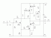
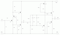
I was checking out a thread in the tubes section here regarding someone wanting a nice preamp circuit that could use a couple of 6CG7s he had on hand (nice tube). He was referred to a page on the Aikido preamp. I was looking at something similar for FETs (J and MOS). They're not totally applicable because of their generally pentodish nature, though some of the smaller SIT devices might work well in this application. At any rate, the usual jfets and mosfets yield up too much gain for use in the unadorned Aikido. What can one one do with all that gain? Well, you can feed it back. With that in mind, here is the result of some doodling around in PSpice. I omitted the RC circuit used for ripple cancellation - you can add it if you think your Vcc supply might be too ripply/ noisy. The circuit simulated as having a THD a little South of 0.001%. As per usual, simulations and reality may differ - I'm still struggling with the circuit that started this thread tying to get something that might approximate the simulated THD results. At any rate, it's more grist for the mill...
Attachments
One possible use for the circuit in the previous post might be to use it in an RIAA amp as an active equalization second stage. Circuit minus values (haven't figured them out yet) is shown here. A hint - LTSpice is free....
Attachments
Last edited:
- Status
- This old topic is closed. If you want to reopen this topic, contact a moderator using the "Report Post" button.
- Home
- Source & Line
- Analog Line Level
- If You Don't Have a SIT, Fake It...
