I'm programming some things for PC based loudspeaker crossovers and the following question/problem popped into my head:
How do you achieve fine control on (digital) delay smaller than one sample period?
To review: at least from what little I know about DSP code, delay is typically achieved through a delay line implemented as a circular buffer. In this arrangement samples are put into a circular buffer and then read out some number of samples later. As long as you want to delay the data by an integral number of sample periods this works perfectly: you just let the buffer chug along until that number of sample periods has elapsed and then you retrieve your data. This works very well.
Let's think a little bit about the resolution of a simple delay line. Samples are coming each (sample rate)^-1 seconds. For example, if your sample rate is 48kHz, every 1/48000 seconds or 2.0833x10^-5 or 0.02083 milliseconds new data arrives. As long as you can live with a delay that is some multiple of this, you can use the simple delay line. But if you want, for instance, to delay by 0.1 milliseconds you need to delay the signal by 0.1/0.02083 samples or 4.8 samples. You need a fractional delay line to be able to do this.
Why bother with this? What's the "problem" here? Isn't digital delay pretty much standard, well-established stuff? Well, yes, and no. It will not matter if the desired delay corresponds to many, many sample periods because the error in rounding to the nearest integral sample would be negligible. For instance if I want to delay my signal by 0.1 seconds I need to delay by 4800.77 samples. By truncating to 4800 samples you incur an error of only 0.77/4800 = 0.016 percent. No problem.
For loudspeaker crossovers, digital delay is often used to tweak the phase alignment between drivers after the crossover filters have been applied. The designer would like to make the phase of a pair of drivers that are operating together within some band of frequencies (e.g. around the crossover point) very similar so that the wavefronts sum in phase. The delays needed for this application are typically on the order of 1ms or less and having to live with delay values that are integer multiples of the sample period is very limiting in terms of phase (depending somewhat on the frequency band). For this reason, the ability to set the delay to some fraction of a sample period would be very useful.
From what I have seen in code for delay lines, the user is tricked into thinking that any delay is possible. The user is able to supply a value for the delay that is a 'float', that is a real number. Inside the delay line code, this is just rounded or truncated to an integral number of sample periods. Since the delay implementation is just a black box, the typical user is clueless about this phenomenon. Since the delay time needed for phase adjustment in crossovers is small, the error introduced by the truncation can be quite large.
It seems that we can turn to interpolation to fix this. Want to delay by 5.5 sample periods? Just interpolate linearly between sample 5 and sample 6 and you have your answer, right? Unfortunately this introduces error that results in significant distortion at higher frequencies, so we need a more sophisticated technique. This could be a higher order smooth interpolation technique, like spline interpolation. Cubic (3rd order) spline interpolation has been used in sample rate conversion for instance. Higher order spline interpolation might be worth trying. Since the delays are often small, it might not even be necessary to use a circular buffer.
I'm guessing that there are other approaches that are used for sample rate conversion but I am not really familiar with these, so I'd like to get some input from the community. I'm hoping people will chime in on this, and other approaches that might work well on this problem.
If you have any ideas on how to best code a fractional delay line, please let me know and/or point me to some background info or papers on the subject.
Perhaps you may want to look at papers on adaptive resapling by Fons Adriaensen Kokkini Zita - Papers . This very clever guy is behind adaptive resampling plugins for jackd which allow to merge two soundcards with independent clocks. His code does what you need - it resamples in between the incoming samples. Your case is a special one of his focus - the output clocks are synchronous, just time-shifted to the incoming samples.
Audio playback/processing in PC is clocked by the soundcard clock. The card is a consumer and when it issues a command (IRQ), the whole chain starting from the end provides new samples in batch (period (alsa)/frame (asio) size). The DSP processing is not done in precise time moments, but in batches which are buffered further down the line, waiting to be transfered/consumed by the card itself via DMA.
To time-shift, you can shift (i.e. delay as a result) samples of one channel in the buffer (time shift at sample granularity). If you need sub-sample time shift of one channel against the other (both consumed by the same clock, at the same moments and rate), you have to resample the stream (of course in batches) to create new samples fitting in between the samples. And that is where Fons'es code could be a hint, IMO. Or perhaps you can get in touch with him, I have seen him on linux audio mailing list http://wiki.linuxaudio.org/apps/all/lad
Digging a little into the subject via Google, it looks like people made this connection over 20 years ago. The much-cited article "Splitting the unit delay - tools for fractional delay filter design," by Timo I. Laakso, Vesa Välimäki, Matti Karjalainen, and Unto K. Laine appeared in IEEE Signal Processing Magazine, January 1996 (vol. 13, no. 1).
It appears that there are several approaches via IIR or FIR. A few of these are:
FIR of modest order: Lagrange (polynomial) interpolation
FIR with large N: Windowed Sinc filter
IIR of modest order: Thirian all-pass
I will look into these in more detail and post again.
It appears that there are several approaches via IIR or FIR. A few of these are:
FIR of modest order: Lagrange (polynomial) interpolation
FIR with large N: Windowed Sinc filter
IIR of modest order: Thirian all-pass
I will look into these in more detail and post again.
Digging a little into the subject via Google, it looks like people made this connection over 20 years ago. The much-cited article "Splitting the unit delay - tools for fractional delay filter design," by Timo I. Laakso, Vesa Välimäki, Matti Karjalainen, and Unto K. Laine appeared in IEEE Signal Processing Magazine, January 1996 (vol. 13, no. 1).
It appears that there are several approaches via IIR or FIR. A few of these are:
FIR of modest order: Lagrange (polynomial) interpolation
FIR with large N: Windowed Sinc filter
IIR of modest order: Thirian all-pass
I will look into these in more detail and post again.
If you don't have IEEE access, here's another free reference.
http://users.spa.aalto.fi/vpv/publications/vesan_vaitos/ch3_pt1_fir.pdf
http://users.spa.aalto.fi/vpv/publications/vesan_vaitos/ch3_pt3_allpass.pdf
Last edited:
Hi,
There are ways around the problem that in most systems
is a bit beyond what the system is actually doing.
Passive speakers use assymetry of the acoustic x/o to
correct phase for non-aligned drivers, (flat baffle) with
consequences for the subsequent vertical symmetry.
However some passive speakers use an all pass delay
to avoid this problem. In the digital realm its obvious
you can combine the two. As long as the delay hits
ballpark, minor asymmetry can fix minor issues,
with minor effect on the vertical symmetry.
No idea though if the system is that clever. Fixed
function active x/o's with adjustable delay ignore
the actual acoustic x/o functions, and even if
not accurate ~ delay will fix the major issues.
rgds, sreten.
the problem is simpler if you delay the tweeter by integer samples and implement any fractional delay in the low pass design to get the net required deltaT
Yes, I am aware of asymmetric filter slopes or using the delay of additional filter stages to tweak the phase and group delay in an effort to get the phase angles to align. That is in the realm of the "art of implementation".
What I want is to be able to provide users a DSP tool that is capable of providing fractional delay so that, if a user wants it, it is available. It is up to the user to choose their crossover implementation.
I'm currently looking into an approach that combines some of the Thirian all-pass ideas with my biquad coefficient optimization stuff. The problem that I see is that IIR all-pass filters are deviating at frequencies above 0.1*Fs from the analog filter phase response that one desires. This is similiar to what I have posted about recently for the magnitude response of other IIR filter types, except it's just the phase response since for the AP filter magnitude is always 1.0. It's this very property, and faster computation, that makes me want to stick to IIR filters. It's simply unfortunate that "as is" the IIR all-pass is not great for flat delay to high frequencies.
One of the ideas behind the Thirian AP design is that you can't have a workable AP filter that delays the signal by d=0.5 sample periods (for example) but you CAN have one that delays the signal by N+d sample periods, where N is a whole number and d is the (desired) fractional part. So, I plan to look into chains of AP filters with "optimized" parameters (e.g. Fc and Q) or optimized coefficients (stability?) such that I can get my fractional delay part. I have to accommodate whatever N is needed to get the desired d, however, it is pretty trivial to implement N-sample delay lines for all the other channels since N is small. This would increase overall latency a bit, maybe by one or two milliseconds, but I don't really care because I am only worried about relative delay and am not worried about latency.
Thoughts?
Thoughts?
I had some success today with Python's scipy.optimize.brute brute force optimizer. Initial conditions still are important but if you have a specific problem one could do worse than tinker around for an afternoon.
Last edited:
OK, I had a little time to experiment and the results look encouraging, at least for the "optimization of the all-pass filter parameters" approach.
I set up two AP filters in my ACD tools, giving an overall filter order of 4. ACD calculates the filter phase responses, which are then unwrapped, and then the group delay is calculated --> this is the quantity of interest. A true "digital delay" has frequency independent group delay. I set up a few cells in which I can enter the integral (N) and desired fractional (d) parts of the delay in units of sample periods. Following Thiran I choose the delay target for optimization so that the overall delay is in the interval N-0.5 to N+0.5. For instance if N=4 (fourth order overall; the product of two second order AP filters) and d=0.7 the target will be 3.7 sample periods.
I created an error function based on sum of squared errors with a weighting function. I needed to include the WF because there is no way that you can expect the group delay to remain constant all the way up to Nyquist. But I don't want to just let it run wild above some cutoff either. So I slowly "loosen" the constraint in the error function by decreasing the weighting above some frequency, which I chose to be 10kHz in these trials.
With the problem all set up, I let SOLVER optimize the Fc and Q of the two filters to minimize the error.
This works pretty well, in fact darn good. The delay is flat up until around 10k where it rises or falls depending on what the optimizer thought was best. This is fine, since the intent is to get flat group delay within the crossover region and 10k is well above this for a loudspeaker. Outside of the crossover region I am not concerned if group delay is constant or not.
I tried various fractional delays, let solver go to town, and it spit out a very good fit to the target each time. Fc and Q for each filter are displayed, and I can see how close to the desired delay I get (at DC). I haven't yet plotted up residuals and all that. Once I do some more experimenting I will post the results, but it looks encouraging so far.
I'm programming some things for PC based loudspeaker crossovers and the following question/problem popped into my head:
How do you achieve fine control on (digital) delay smaller than one sample period?
.........
If you have any ideas on how to best code a fractional delay line, please let me know and/or point me to some background info or papers on the subject.
Hi Charlie,
Multiply your filter response (both real part and imaginary part) by exp(-jwt)
t = actual delay time
w = 2*PI*f
f = you should be able to work it out
Best Regards,
Bohdan
Hi Charlie,
Multiply your filter response (both real part and imaginary part) by exp(-jwt)
t = actual delay time
w = 2*PI*f
f = you should be able to work it out
Best Regards,
Bohdan
Hahaha. You crack me up with such an accurate and concise, yet useless, answer.
Multiple exactly what filter response? There's no analytical continuous time filter here. I need to perform some operation(s) on a stream of discrete time domain samples, so I think that the options are FIR or IIR filtering, no?
Currently I am working on the IIR angle and it seems to be working pretty well given some ground rules. More on that later.
I assume that this could be done via FIR with "alot" of taps. Unfortunately I want this to be a computationally "light" application (I'm using a Raspberry Pi), so again I assume that this is probably not viable. I have to admit that I am not all that familiar with FIR filters (OK not at all really)- could you or someone else estimate how many taps would be required if one wanted to delay by a fraction of a sample period while leaving amplitude undisturbed (less than 0.1dB variation)?
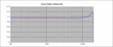
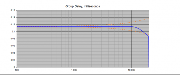
Here are some examples of what I have been able to do with some IIR allpass filters. It's 5th order overall. The fractional delay, following Thiran, must be between about 5-0.5 and 5+0.5 sample periods, e.g. between 4.5/Fs seconds and 5.5/Fs seconds. Going outside of this range is possible but increases the deviation from the target group delay at high frequency.
I have attached a couple of plots showing the typical group delay response for these kind of filters. Amplitude is always exactly 1.0 for these filters. There is a plot of a flat line with the high frequency group delay tailing "up" and another with the high frequency tailing "down". This is the general behavior towards 4.5 and 5.5 sample periods, respectively. As the fractional delay gets closer to 5 sample periods the group delay at high frequency flattens out. This is because the AP filter simply reduces to a delay block.
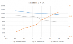
I ran through the range (4.6 to 5.6 sample periods) while optimizing parameters of the filters and the I plotted these versus delay-5, e.g. from -0.4 to 0.6. I have also included this plot. What's interesting is that the trend in the parameters is almost linear. It may be the case that these are really linear, but the optimization is reaching a local minimum. It would be possible to regress the values and then spit out what they should be as a function of the fractional delay that is desired. That would eliminate the need to optimize at all. You would get a closed-form solution so to speak, which is exactly what I would like to have.
So, this all looks interesting and encouraging to me and is something that I can implement using standard IIR AP filters.
I have attached a couple of plots showing the typical group delay response for these kind of filters. Amplitude is always exactly 1.0 for these filters. There is a plot of a flat line with the high frequency group delay tailing "up" and another with the high frequency tailing "down". This is the general behavior towards 4.5 and 5.5 sample periods, respectively. As the fractional delay gets closer to 5 sample periods the group delay at high frequency flattens out. This is because the AP filter simply reduces to a delay block.
I ran through the range (4.6 to 5.6 sample periods) while optimizing parameters of the filters and the I plotted these versus delay-5, e.g. from -0.4 to 0.6. I have also included this plot. What's interesting is that the trend in the parameters is almost linear. It may be the case that these are really linear, but the optimization is reaching a local minimum. It would be possible to regress the values and then spit out what they should be as a function of the fractional delay that is desired. That would eliminate the need to optimize at all. You would get a closed-form solution so to speak, which is exactly what I would like to have.
So, this all looks interesting and encouraging to me and is something that I can implement using standard IIR AP filters.
Attachments
Interesting note:
The response from these IIR allpass filters is remarkably different than analog allpass filters with the same parameters, which in general have a group delay that falls off MUCH earlier.
If the desired outcome is to use the IIR allpass to obtain flat group delay up to about 0.25*Fs (in this case to about 12k with Fs=48k) then we are in luck - the behavior of the IIR allpass actually HELPS by extending the flat delay region above what you would get for the same filter implemented via analog means.
After a little more programming time I finally was able to implement the Thiran AP filter. I played around with orders up to 8. Wow, these a pretty good. I suppose that is why they are called "optimal", eh? So it looks like this is what I will implement. It's a light weight IIR solution.
Hahaha. You crack me up with such an accurate and concise, yet useless, answer.
Multiple exactly what filter response? There's no analytical continuous time filter here. I need to perform some operation(s) on a stream of discrete time domain samples, so I think that the options are FIR or IIR filtering, no?
Each element of your new filter. The delay is the Fourier transform equivalent of a time delay. Convolve in time, multiply in frequency.
I'd think Bohdan knows what he's talking about theoretically and practically, given his implementations in SoundEasy.
Each element of your new filter. The delay is the Fourier transform equivalent of a time delay. Convolve in time, multiply in frequency.
I'd think Bohdan knows what he's talking about theoretically and practically, given his implementations in SoundEasy.
Bodahn does know what he is talking about. His post was just not germane to what I am trying to do, although completely accurate.
I'm not going to even think about doing any convolutions! Yikes, that's way too computationally intensive for the low power processors that I am using...
I think there's a communication breakdown. ")
Time delay would get convolved with the time signal, which after a Fourier transform is a multiplication. Your filter curves could ostensibly be done via convolution as well, but your (understandable) optimization is to work in the frequency domain.
All he is saying (and I'm parroting) is that if you want a fixed time shift, you multiply your IIR filter coefficients by the equation he gave you. That's it. Super easy.
All he is saying (and I'm parroting) is that if you want a fixed time shift, you multiply your IIR filter coefficients by the equation he gave you. That's it. Super easy.
IIR doesn't work that way. An IIR uses the finite difference equation directly. Yes you could plot the impulse response of an IIR filter take the FFT and rotate the frequency domain component and transform it back, but then you are left with an impulse response and convolution again. There are only 5 coefficients in an IIR biquad there is no simply multiplying them to get 1/2 sample delay.
I think he was simply implying, "why not switch to FIR because it's easy to do this?"
my earlier point of integer sample dealy for the treble because that's just a delay line which simply works amounts to mixing in a few "fir" stages
and then implementing any fractional delay for the low passed lower frequency drivers - which possibly could be all pass iir biquads - but could also be short (asymmetric, "time interpolating") fir because you only need flat response up to the lower XO frequencies
and then implementing any fractional delay for the low passed lower frequency drivers - which possibly could be all pass iir biquads - but could also be short (asymmetric, "time interpolating") fir because you only need flat response up to the lower XO frequencies
- Status
- This old topic is closed. If you want to reopen this topic, contact a moderator using the "Report Post" button.
- Home
- Source & Line
- PC Based
- IDEA: fractional delay line using sample rate conversion techniques?