yes but that^ is how myths are born. people could take what you wrote as fact.
I really, really doubt that the guys at Burson have actual silicon fabrication experience. IME many of theses arguments are like the Win vs Linux ones: they're based on facts from 20 years ago. Win 95 or worse vs *nix systems of the day, somehow failing to remember that there have been a few major advances since.
what the Burson guys are doing is IMO an offshoot of the "subjectivist" movement. once it was about "when measurements fail, just listen". now it's "just forget all the well established facts and reinvent everything from scratch, doing it as badly as possible".
Last edited:
See the parts circled in blue below. Is that what you mean by "reverse biased mosfets"?many are reverse biased mosfets
P.S. Nevermind the extraneous question in the pic - I swiped the pic from an unrelated thread in another forum.
Attachments
And you think I google as I read along the forum like yourself or quote someone who doesnt know what he is talking about ??
I learnt this during 3rd year electrical engineering degree.
This is not the area of my expertise and I have no interest in it (note: doesnt mean Im clueless about it).
I didnt stumble upon the information of MiM caps, ive been looking into the feasibility of taking something like this on as a longer term goal. I'm not yet skilled enough in circuit and PCB design and modeling to throw a few grand at something when I can buy something excellent for a few dollars; but the idea is certainly very interesting to me and something I intend to work towards.
I knew of the linearity, not just because i'm already using trickledown parts (thin film caps, highly linear passivated die fets and thin film resistors), but because of the difficulty in measuring performance of parts today, real non-magical and affordable parts, which suggests some inherent linearity in the devices they are composed of; as well as suggesting that the processes involved are nolonger the cutting edge.
What I did use google for was to search out PiP caps, as there are both thick and thin film variants and i'm not yet experienced with the parts on offer.
better to use google and the edaboard search function and have some idea how mature the technologies are, than spout what is likely decade old second hand knowledge is it not? or you are happy with how that panned out for you?
Manso, my comment was satorical leaning heavily towards the cynical. IC's are used in many high end, very sensitive applications within the electronics world with no problem, as are X7R capacitors and other modern components (even surface mount resistors) yet these and other components aand design techniques are not suitable for audio. So having recently heard that a voltage regualtor that modulates the DC won a listening contest and other threads I have been involved in I believe that coloration of the sound is realy what true audiophile desire, so that it sounds different.
I wonder how long IC's take to burn in, and does it depe3nd on the technology used (90nm, 45nm etc).
Qusp, these have some interesting stuff and pretty pictures on MEMEs etc, dont think it is published anymore, but use to enjoy looking at the pictures everymonth when my copy arrived.
Small Times Past Issues: ElectroIQ.com
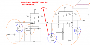
See the parts circled in blue below. Is that what you mean by "reverse biased mosfets"?
P.S. Nevermind the extraneous question in the pic - I swiped the pic from an unrelated thread in another forum.
Even so, it seems an interesting question. My first thought is that they are using the gate capacitance of the MOSFET as a high frequency stabilizing element, instead of using a simple capacitor. Perhaps, the non-linear behavior of the gate capacitance compliments the non-linear behavior of some other circuit element. However, I'm merely guessing.
Last edited:
Ken, I dont think you are far from the mark, Scott Wurcer was saying that they wire transistors as diodes for the same reason, that they will track the other transistors more closely. so I could see that as a possible reason anyway.
marce: I hope you got that the reference to MEMS was a somewhat obscure and farcical suggestion that I should be looking into using MEMs springs or something to damp the potential non-linearities that ICs inflict on themselves and the signal")
very interesting stuff though and its a boom currently, the MEMs catalogue at mouser is massive and growing every day.
marce: I hope you got that the reference to MEMS was a somewhat obscure and farcical suggestion that I should be looking into using MEMs springs or something to damp the potential non-linearities that ICs inflict on themselves and the signal
very interesting stuff though and its a boom currently, the MEMs catalogue at mouser is massive and growing every day.
FIRST... "reverse biased MOSFETs" ... what? There are no MOSFETs in 99.9% of all OpAmp designs. Even the very, very newest - no MOSFETs. Sure, in class D systems, MOSFETs dominate the output-driver section. Wisely. But not internals of OpAmps.
So, whatever cockamamie objection you have viz a vis MOSFET gate capacitance linearity ... just isn't valid in the context of what we're talking about re: OpAmps.
SECOND... I think there is "design envy" in the majority of people who endlessly diss modern well designed OpAmps. Someone here blithered "80 transistors when 10-15 would be better", which is just bullsnot. Every last transistor - and I mean every one of them - has a defined role, an action it performs. That reading an OpAmp circuit schematic is all-but-impossible (because of the remarkable number and type of exotic chip-scale circuit features that only IC designers need, or want), does not constitute a validation of dissing the design(s).
THIRD: I too designed analog ICs for a bit ... back when they cost many hundreds of thousands of dollars to make prototypes. The things being done today that make "modern" ICs so darn compelling relate to the process itself, and not so much the design. Design of course is critical - but getting repeatability in a whole manufacturing line has been the revolution. My original point was, (with the example 2 MHz minimum versus 5 MHz typical gain-bandwidth-product) ... those wide ranges are both historical, and to allow for fairly wide variation in substrate silicon characteristics. In practice, the actual GBP is much tighter. Just don't DESIGN close to the 5 MHz window! Assume 2 MHz, and every chip you insert in the circuit will work. As designed.
Anyway - this thread seems to be devolving into something not-so-fun anymore. Sorry.
GoatGuy
yes but that^ is how myths are born. people could take what you wrote as fact.
I really, really doubt that the guys at Burson have actual silicon fabrication experience. IME many of theses arguments are like the Win vs Linux ones: they're based on facts from 20 years ago. Win 95 or worse vs *nix systems of the day, somehow failing to remember that there have been a few major advances since.
what the Burson guys are doing is IMO an offshoot of the "subjectivist" movement. once it was about "when measurements fail, just listen". now it's "just forget all the well established facts and reinvent everything from scratch, doing it as badly as possible".
But what I posted is not a myth, it is (was) fact although it may be a bit outdated.
It doesnt however mean we should trade a distorted truth for another distorted truth. There are many trade-offs and the fabrication process has many limitations. The word mostly used by authors and fabrication designers of IC opamps is "assimalate the performance" which basically means resemble the discrete parts. I dont believe passives especially capacitors formed during the most modern processes can as yet offer the same performance as can be had by discrete, although todays ICs do have truely excellent performance mainly due to the circuit design, high performance active devices and close mathing of these.
So in a way we can say as Sy put it that the IC passives are "good enough" to achieve the very high levels of performance of modern opamps I have to admit.
I feel what Burson is doing is worse, its twisting the truth eg not telling the whole truth eg LYING. However there will always be some that will be fooled and thats why they are still in business.
For Sy here are some excellent reads about the subject. In my short lunch hour I was unable to find the reference which covered the subject extensively with a few chapters but these give a good idea.
- Trade-Offs in Analog Circuit Design by Chris Toumazou and George Moschytz
and Barry Gilbert.
- Analysis and Design of Analog Intergrated Circuits by Gray Mayer
- Bipolar and MOS Analog Integrated Circuit Design - Grebene
- Analog and VLSI Circuits by Wai-Kai Chen.
Note these do date from the early 1990s to around 2003 so tech has probably advanced since then.
FIRST... "reverse biased MOSFETs" ... what? There are no MOSFETs in 99.9% of all OpAmp designs. Even the very, very newest - no MOSFETs. Sure, in class D systems, MOSFETs dominate the output-driver section. Wisely. But not internals of OpAmps.
So, whatever cockamamie objection you have viz a vis MOSFET gate capacitance linearity ... just isn't valid in the context of what we're talking about re: OpAmps.
SECOND... I think there is "design envy" in the majority of people who endlessly diss modern well designed OpAmps. Someone here blithered "80 transistors when 10-15 would be better", which is just bullsnot. Every last transistor - and I mean every one of them - has a defined role, an action it performs. That reading an OpAmp circuit schematic is all-but-impossible (because of the remarkable number and type of exotic chip-scale circuit features that only IC designers need, or want), does not constitute a validation of dissing the design(s).
THIRD: I too designed analog ICs for a bit ... back when they cost many hundreds of thousands of dollars to make prototypes. The things being done today that make "modern" ICs so darn compelling relate to the process itself, and not so much the design. Design of course is critical - but getting repeatability in a whole manufacturing line has been the revolution. My original point was, (with the example 2 MHz minimum versus 5 MHz typical gain-bandwidth-product) ... those wide ranges are both historical, and to allow for fairly wide variation in substrate silicon characteristics. In practice, the actual GBP is much tighter. Just don't DESIGN close to the 5 MHz window! Assume 2 MHz, and every chip you insert in the circuit will work. As designed.
Anyway - this thread seems to be devolving into something not-so-fun anymore. Sorry.
GoatGuy
Not another one
.Please read the books I have given in post 68 and learn how caps are formed in ICs.
Fortunately, those guys know the difference between VLSI for memory/processors and analog chip fabrication.
Same as post 69.
Do you think that a mosfet capacitor is formed via different technology, process or way in VLSI as opposed to a analog one ??.
Last edited:
See the parts circled in blue below. Is that what you mean by "reverse biased mosfets"?
P.S. Nevermind the extraneous question in the pic - I swiped the pic from an unrelated thread in another forum.
Most probably yes. Ken Newton is right on the money. It however is not my area of expertise as stated before. In the references in post 68 youll also be surprised to find how high hfe pnp transistors are formed as well as many other passives and actives.
Early chips had problems due to the rubbish lateral pnps. Then 30 years ago Harris cracked dielectric isolation and making good pnp devices. Since then good chip designs have been excellent.
Regulators are hard to use properly. They all have poor high frequency rejection and need a simple RC or LC low pass on the input. Many are only truly stable over a rang of load resistance and capacitance. Too good decoupling can cause instability, so capacitor swappers sometimes are actually causing oscillation
Regulators are hard to use properly. They all have poor high frequency rejection and need a simple RC or LC low pass on the input. Many are only truly stable over a rang of load resistance and capacitance. Too good decoupling can cause instability, so capacitor swappers sometimes are actually causing oscillation
Same as post 69.
Do you think that a mosfet capacitor is formed via different technology, process or way in VLSI as opposed to a analog one ??.
yes, not another one...
are you deliberately misunderstanding whats written? Sy's point was clearly that the process is aimed at VLSI and logic, so the decoupling caps linearity for linear analog signal processing is not so critical... thus its lucky for us and them that they understand that they can use a different technology/feature more suited to the goal
I state again, thin film caps are VERY linear. also lucky that well designed opamps dont usually call for all that many, or all that much capacitance... if large amounts are required, such as that for bypassing a low noise reference they usually provide a pin for it so you can install one on the PCB...
Last edited:
Qusp, I am currently operating at about 0.001% of my normal inteligence so missed the sarcasm. But the pictures and descriptions of what they do with MEMs I do find facinating. I also had a little role in an energy harvesting experiment for soldiers, where mems were suggested by some, a generator in the boot heal was the most efficient, the wiring was unreliable in adverse conditions though.
Manso ... you seem to be intentionally "missing the point" entirely: Silicon OpAmp design utilizes no internal capacitors, MOSFET or otherwise. If there's anyone that needs to read here, buddy, it is you. Please, do try.
In order to "counter" this point of view, we don't need a reading list of good, if but somewhat outdated university textbooks. We need you to produce a couple of OpAmp (IC) design schematics that demonstrate the signal-path application of MOSFET capacitors, on the chip itself. I know of none. Your position RESTS on there being these bad-boys; yet, if you can't produce a schematic, then you're just tilting at windmills.
So... on you, buddy.
GoatGuy
Qusp, I am currently operating at about 0.001% of my normal inteligence so missed the sarcasm. But the pictures and descriptions of what they do with MEMs I do find facinating. I also had a little role in an energy harvesting experiment for soldiers, where mems were suggested by some, a generator in the boot heal was the most efficient, the wiring was unreliable in adverse conditions though.
hehe, no worries, it was pretty vague, you know that point where a joke gets carried on too far, well I think I reached it
yes I find it fascinating as well, I may actually look at the sensors for an upcoming MCU project for something different. Energy harvesting is for sure an obvious use of it if they can be deployed in useful numbers.
yes, not another one...
are you deliberately misunderstanding whats written? Sy's point was clearly that the process is aimed at VLSI and logic, so the decoupling caps linearity for linear analog signal processing is not so critical... thus its lucky for us and them that they understand that they can use a different technology/feature more suited to the goal
I state again, thin film caps are VERY linear. also lucky that well designed opamps dont usually call for all that many, or all that much capacitance... if large amounts are required, such as that for bypassing a low noise reference they usually provide a pin for it so you can install one on the PCB...
No. I think you are deliberately changing the subject, I did not once mention anything about decoupling caps and do not see Sy mention this anywhere. Further the process is intended for either VLSI or IC OPamp.
Actually if I remember correctly mosfet caps "can" be made even more linear than thin film, the trade off is voltage-coefficient.
http://www.analog.com/static/imported-files/data_sheets/AD797.pdf
Since you won't get specific, I will, using a very common chip for audio. There are two capacitors here (Figure 32). Are you maintaining that they're MOSFETs? If so, what are the "hiccups"? How would you predict that they affect the circuit performance? In all of the performance graphs here and on Groner's site, what are the experimentally determined consequences of these "hiccups"?
Fortunately, the designer of that chip is an active participant here and can check your answers.
Snarky posts...
Well, there you are. Snarky answer containing no value. Also, no schematics to demonstrate. I found exactly ONE schematic after some looking about that references an on-chip capacitor to act as a frequency compensation component - above 1 MHz, as per the ancient 741. And it isn't a MOSFET capacitor, reverse biased or otherwise. Indeed ... the majority of older OpAmps had separate pins specifically for external compensation capacitors - because there was a particular spot in the circuit where they would best be connected.
Point is ... your MOSFET capacitor theory of badness ... appears to be without support or basis.
GoatGuy
Yes I know, frequency compensation is done with gamma rays from the planet Jupiter.
Well, there you are. Snarky answer containing no value. Also, no schematics to demonstrate. I found exactly ONE schematic after some looking about that references an on-chip capacitor to act as a frequency compensation component - above 1 MHz, as per the ancient 741. And it isn't a MOSFET capacitor, reverse biased or otherwise. Indeed ... the majority of older OpAmps had separate pins specifically for external compensation capacitors - because there was a particular spot in the circuit where they would best be connected.
Point is ... your MOSFET capacitor theory of badness ... appears to be without support or basis.
GoatGuy
- Status
- This old topic is closed. If you want to reopen this topic, contact a moderator using the "Report Post" button.
- Home
- Source & Line
- Analog Line Level
- IC's get hammered