Hi,
I'm trying to see if an Icepower 500A module pulled from a subwoofer is working. The original SMPS is definitely not, so I'm testing it using a linear supply from a Pass F3 build at around 53V (without load) and a +/-12V regulated supply built on perfboard using 7812/7912 type regulators. I think I've got everything connected as the datasheet says.
There's no sound, which may mean it's dead of course, but my question is what voltage I should be seeing on the Mute and Standby pins. The datasheet says the board pulls these "high" automatically, but I'm measuring 0.7 and 0.6 volts, which doesn't seem very "high" to me; I would have expected 3.3V or 5V, or something. If these are low then it might mean the board is duff, or maybe needs to be "reset" somehow, perhaps by pulling them high? (Although the datasheet is pretty clear this is meant to be automatically done by the board.)
Any help much appreciated.
Nigel
Thanks, Jan. The datasheet says the standby pin is active when pulled low, and I think the same is true for the mute pin although I couldn't find it in the text when I looked now. (I'll take your word on the bar; I don't have the experience to decipher that.) So they should be high in normal use, and low when the output is muted or device in standby. RIght? Would you agree that whatever else is the case, 0.7 and 0.6V can't be "high"?
Either way you're right that it can't hurt to try pulling them up. I presume this means +12V, right? There are two supplies to the amp, but the high current 53V supply (or 80V from original PSU) doesn't sound right to me. +12V shouldn't destroy anything that isn't already done for, but 53V might.
Best
Nigel
I do not think that it will survive 12 V, if it is similar to the 125ASX2. This one has an internal pull up. The pin will be pulled down internally through a transistor (except for a 0.7 V voltage drop) when the protection circuitry activates. Logic levels are +5 V and 0 V.
The 0.7 V suggests that the protection circuitry has activated, unfortunately.

The 0.7 V suggests that the protection circuitry has activated, unfortunately.
Last edited:
Fig 14 & 15 make it clear that they are referenced on Vcc which presumably is the high voltage V+.
So you'd need to pull them up to that.
Correction: it says: Vcc JST** Pin numbering Positive power supply input for the signal section.
So that's NOT the high voltage supply.
It looks like YOU have to provide Vcc and Vss, and if you don't it won't work.
Table 3 says you need to provide +/-15V. See table 4 for the specs. So your amp probably is fine.
Jan
Last edited:
TBTL: That would explains the 0.7V! So it sounds like the protection circuitry is activated. If I understood the datasheet correctly, the protection circuitry is meant to be briefly activated during powerup, and then the pin is pulled high by the board and you get sound. If something is broken and the board isn't doing that then the 0.7V is explained. Of course the board may have triggered the protetction circuitry because of something I've done, I guess... so I'd better check things again. (This is the 500A, not the 125ASX2, but I doubt that makes a big difference.)
Jan: Now you point it out, Fig 14 and 15 are pretty clear; thanks. But the datasheet uses Vcc to refer to the 12V supply; the -12V supply is Vss, and the high voltage 80V supply (or 53V in my case) is denoted Vp. So unless I've misunderstood (always a possibility! Please correct me if so!) I should try pulling it up to the +12V.
Thanks
Nigel
I think maybe I wrote while you were both responding.
I have +/- 12V as Vcc and Vss, and AGND is connected to the 0V on the dual PSU I put together on perfboard. Table 3 shows max ratings of +/-15V for Vcc and Vss; according to table 4 I'm OK with +/- 12V. I'm also above the minimum of 42V for Vp specified in Table 4, since I'm supplying 53V. (I figured this should be fine for testing purposes.) All voltages are correct on the input connectors, as shown on table 2. Since I'm using a single-ended input for testing I've tied Vi- (the cold half of the balanced input) on pin 6 to AGND on pin 3, which should be OK, I think. And the two outputs Vo- and Vo+ are going tot he test speaker. I'm not accustomed to balanced signals, so if either of these last is wrong please let me know, but I think everything is connected as it should be.
I think TBTL is right and the protection circuit is being activated, so probably something is burned out on the amp board. Something blew the PSU, for sure, so it's quite possible it took the amp out also, although there's nothing obvious wrong visually.
I'll take a closer look at the amp board before proceeding, but unless anything turns up, or anyone has any other suggestions, I'll trying putting 5V on the mute and standby pins and see what happens. If that doesn't work, I'm out of ideas so I might as well try 12V, like Jan said.
Thanks
Nigel

Certainly Vcc is +12V. And Figures 14 and 15 show Vcc used for mute and standby, as you pointed out earlier.
I'm going to take a close look at the board again, just to see if there's anything I've missed, and then check all my connections again, and then try pulling standby high.. I suspect, however, that something on the board is smoked, or the internal pull-up described in the datasheet should have worked.
Thanks to you both for the help. I'll let you know what happens.
Nigel
Just to be clear, I am using an external +/-12V supply for Vcc and Vss. Table 3 in the datasheet says 15V is a maximum rating for Vcc, table 4 shows "typical" Vcc is 12V, Vss is -12V. I have measured all voltages to the two connectors, as shown in tables 1 and 2, and the supplied voltages are as they should be. (My Vp is 53V instead of the 80V the original PSU gave. That should be OK, though according to table 4, which says a minimum of 42V.)
All seems to be as it should be. Am I missing something from the datasheet? You seem pretty sure I should be providing +/-15V, rather than +/-12V...
Best
Nigel
All seems to be as it should be. Am I missing something from the datasheet? You seem pretty sure I should be providing +/-15V, rather than +/-12V...
Best
Nigel
Vcc/Vss range: 10 to 15 (max). Your choice of 12V is perfect.
Make sure that your external + and -12V are correctly wired to the amp PCB; make sure the common (zero) return is connected where it should be on the amp PCB.
Visually inspect the amp PCB tracks for any damage due to high currents (that may have come from the burnt PS). Check the components as well.
Check the output transistors (no need to remove them from the PCB), for a dead-short... just quick&dirty ohmmeter check.
Mute and Standby are wired as a fail-safe input: the powered-up amplifier will stay in mute / in standby mode if the pins are NOT connected to Vcc (to 12V).
Thanks to all of you. I'm happy to say the amp is working. Let me document it all here, because I think this might be helpful to other people with this amp board in avoiding my mistake. (Yes, human error, as usual in this house...)
The first attachment below is a copy of the datasheet. In table 2 on page 8 it lists the connections (pins 1 through 8) on the JST PHR-08 connector, and notes that the numbering Icepower uses is the reverse of the numbering that JST uses. They don't say why they switched the order, but there you are. So I (naturally) assumed that the markings on the Icepower board would be the ones they say Icepower uses...
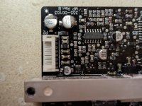
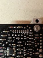
The second and third attachments are photos of the two sides of the board. I was working on the solder side, as in the third attachment; the other side was hidden by the panel the board was bolted to. When I took the board off the panel to check for burnt components I suddenly wondered about the numbering again, and I found that the numbering of the pins is different on the two sides of the board. In other words, the pin marked 1 on the component side is marked 8 on the solder side, and vice versa. You can see in the photos that the pin nearest the aluminium heatsink bar is numbered 1 on the component side, and 8 on the solder side.
In other words, Icepower uses their numbering on the component side but the the JST numbering on the solder side.
So I reconnected the JST connections things in the other order (meaning pins 1 through 8 in table 2 in the Icepower numbering are connected to pins marked 1 through 8 on the component side of the board, not the solder side.) And the amp produced sound as expected.
I'm still trying to imagine why Icepower would number things differently on two sides of the board. Does this make sense to anyone?
Again, thanks to you all for your help.
Best
Nigel
The first attachment below is a copy of the datasheet. In table 2 on page 8 it lists the connections (pins 1 through 8) on the JST PHR-08 connector, and notes that the numbering Icepower uses is the reverse of the numbering that JST uses. They don't say why they switched the order, but there you are. So I (naturally) assumed that the markings on the Icepower board would be the ones they say Icepower uses...
The second and third attachments are photos of the two sides of the board. I was working on the solder side, as in the third attachment; the other side was hidden by the panel the board was bolted to. When I took the board off the panel to check for burnt components I suddenly wondered about the numbering again, and I found that the numbering of the pins is different on the two sides of the board. In other words, the pin marked 1 on the component side is marked 8 on the solder side, and vice versa. You can see in the photos that the pin nearest the aluminium heatsink bar is numbered 1 on the component side, and 8 on the solder side.
In other words, Icepower uses their numbering on the component side but the the JST numbering on the solder side.
So I reconnected the JST connections things in the other order (meaning pins 1 through 8 in table 2 in the Icepower numbering are connected to pins marked 1 through 8 on the component side of the board, not the solder side.) And the amp produced sound as expected.
I'm still trying to imagine why Icepower would number things differently on two sides of the board. Does this make sense to anyone?
Again, thanks to you all for your help.
Best
Nigel
Attachments
Male/female connector mating is confusing stuff... always has been/always will be.
They did it in such a way to make things easier to understand... if you are approaching the PCB socket with an external plug... then it makes sense; not so much if you are fault-finding... I always double-check things with a multimeter... I do a bit of PCB tracing/checking, to make sure I'll not f*&ck up.
That component side solder job is horrendous... the oven was not hot enough... must've been wintertime.
Last edited:
Is this a male/female thing, though? The different numbering is for the same pins on the opposite sides of the board. I did check with a multimeter, but I was working off incorrect information (numbering).
Still, at the end of the day it was my mistake. And had I tried to trace things on the PCB, as you suggest, I'd have taken the board of the aluminium panel sooner, and found the problem.
Still, at the end of the day it was my mistake. And had I tried to trace things on the PCB, as you suggest, I'd have taken the board of the aluminium panel sooner, and found the problem.
Average user Joe is not supposed to look at the PCB pin numbering... just Datasheets.
Then, the pin numbering stated in a datasheet for the socket should match the pin numbering on the plug (the input wire loom) - if it is labelled at that end...
Anyway, I might be wrong.
Important thing? The amp is working.
Then, the pin numbering stated in a datasheet for the socket should match the pin numbering on the plug (the input wire loom) - if it is labelled at that end...
Anyway, I might be wrong.
Important thing? The amp is working.
- Home
- Amplifiers
- Class D
- ICEpower 500A