input surge currents are usually measured in a few cycles of the AC waveform 10-100 msec or so events.
DC feed..from DC to DC converter.
No the reason is to ensure the heaters are high enough resistance to run from the DC converter..I suspect your real concerns are tube life related?
The DC converter will not drive into a near short..no value of simple resistor will work it has to be low mA and increase as the filaments warm up. Or the converter sits down when the relay shorts the NTC..what do you mean trips?
"the power supply" needs a closer look! sounds like there is little to none surge rating allowed IMO
since it's relay driven, you can use a simple power resistor in the 1-10 ohms range to limit surges.
 Yes its PITA..the converter is a potted device so its not adjustable..and it has to have 500V isolation because its an Aikido line stage..
I have just tried a CCS and it doesn't work the tolerance of the Dc converter needs the heaters warm before relay short..the CCS had to be set to low to enable the DC converter to run and the low current was not enough to run the heaters up so the DC converter sits down again..in current limit..I have even put in a variable resistor to find a fixed value that works..and fixed won't work..it has to be NTC..I tried a lamp for a laugh however the current is not enough for the 10 sec time limit..
PWM will be the next try..
There are no transformers its just an experiment..so the dc converters isolate the heaters..so they can be lifted for the top tube in the line stage..
Input is single low voltage DC no AC..
Its obvious the problem is the DC converter...however it works with NTC..its creating the NTC ramp without the heating of an NTC..so there is no reset time due to cool down. Power up half way during cool down and the Dc converter sits down again in current limit due to the supply current being to high.
I could get round it by keeping the heaters warm with a trickle current but that's cheating..
Regards
M. Gregg
Last edited:
what is the DC feed (mother) supply at ? unless off-grid a simple small XFMR will do. safety markings / ratings will meet 500V easily.
yeah almost all DC/DC converters don't do output surges vey well, 130% max due to primary current limits.
you could build a small DC/DC w/o current limit. boost or buck and add an isolated winding. a dozen parts or so.
yeah almost all DC/DC converters don't do output surges vey well, 130% max due to primary current limits.
you could build a small DC/DC w/o current limit. boost or buck and add an isolated winding. a dozen parts or so.
Last edited:
I have just tried a CCS and it doesn't work the tolerance of the Dc converter needs the heaters warm before relay short..the CCS had to be set to low to enable the DC converter to run and the low current was not enough to run the heaters up so the DC converter sits down again..in current limit..I have even put in a variable resistor to find a fixed value that works..and fixed won't work..it has to be NTC..I tried a lamp for a laugh however the current is not enough for the 10 sec time limit..
yeah you bought too wimpy of a converter, not appreciating the variable nature of its load.
yeah you bought too wimpy of a converter, not appreciating the variable nature of its load.
I thought I would just put in a resistor and short it. However its not that straight forward. Its 500mA rated..so you would think it would walk it..Its getting the heaters hot enough from the cold start, however there is an initial point where the heaters don't heat and sit there where they seem to dissipate the energy and it offsets the start. ie heating is dependant on wattage..volt drop..
Its very interesting if also a PITA..Ive done cold starts in many ways before however this is strange..
..its a bit like initially trying to heat a piece of wire..with no resistance. All the energy dissipates in the resistor which is obvious..the resistor is a better heating element than the heater wire.. once you get even a slight change in the heater that's it and you dissipate energy.Regards
M. Gregg
Last edited:
so what is the cold resistance?
similar to buying and inverter for household duty, folks don't consider motor starting currents, isn't printed on the appliances.
Its approx. 23.5 ohms. Series..
Regards
M. Gregg
A capacitance multiplier can give a "sort of" controlled ramp up of voltage.
A current source to the base would give a nice linear voltage ramp.
Its approx. 23.5 ohms. Series..
Regards
M. Gregg
hmmm that's just over rated current 570 mA , pity you couldnt adjust the output voltage to bring it under max power. You could test the SMPS and / or send it back for an replacement/ upgrade.
edit> it's strange a series 5 ohm resistor cant work and get the filament glowing > bad power supply?
Last edited:
hmmm that's just over rated current 500mA , pity you couldnt adjust the output voltage to bring it under max power. You could test the SMPS and / or send it back for an replacement/ upgrade.
Its interesting the running current is .36..
After a few hours of "Fun" I started thinking how hard can it be to emulate an NTC..
Regards
M. Gregg
Last edited:
I will have a look at the capacitance multiplier..
The problem with this is the power dissipated in the transistor..ok its 10 sec...
Regards
M. Gregg
You might be able to add a parallel power resistor across the pass device, if it's really too much.
edit> it's strange a series 5 ohm resistor cant work and get the filament glowing > bad power supply?
Yes I agree,
however it works perfectly with an NTC..its almost like there is some sort of output sense for short..
I have tried 5/10/47 and every variation in between..
Even if you get a start and see the voltage start to rise the heater either sits there soaking it up or climbs so slowly that after 10 sec when the relay cuts in it goes back into CL..
I have watched the NTC and it starts very low..then after about 5 sec you see the voltage across the heaters rise very fast.
Regards
M. Gregg
Last edited:
something aint right, test the power supply for rated current! and then cycle it on/off
You got that right!
You got me thinking, where is the current going...
Well I forgot<<yes believe it or not that I was charging a cap at start up from the DC converter as well as the soft start..the original idea was to dump the charge into the heaters at start up when the relay closed.
However when the system failed the cap was discharged through the heaters (relay closed now the cap is directly across the heaters)which were now a low resistance so the converter was trying to drive current into the heaters and charge the capacitor with a dead short across it via the heater filaments..
No wonder it didn't make sense..
So it is now working..I must just switch it on and off a few hundred times to convince myself..click click..click ..click..
I will probably look at the PWM just for interest..Thank's to all who put forward their ideas much appreciated..its always the obvious that you don't see
Thinking the cap is charged and will not be an issue..well it isn't until its shorted by the heaters at low resistance..can't believe I overlooked it!
Regards
M. Gregg
Last edited:
Hi Guys
A voltage source that is set to current clamp a little above the operating current will provide a soft-start for filaments and works very well there is no need to set time constants, etc.. Of course, this is much easier to implement with DC filaments, but... you can use mosfets to control AC currents.
Have fun
Well I forgot<<yes believe it or not that I was charging a cap at start up from the DC converter as well as the soft start..the original idea was to dump the charge into the heaters at start up when the relay closed.
Hi glad you can proceed on your project,
I always advise with SMPS and adding largish output caps, there should be a warning, for many reasons! it rarely buys you anything but problems. It has higher sampling / charging, feedback, and current limit! this isn't 100/120 Hz brute force linear unregulated supplies.
Last edited:
I have to admit that I do not see quite clearly what your problem was, and how you solved it... I understand it has to do with a cap, but other than that I am lost.You got that right!
You got me thinking, where is the current going...
Well I forgot<<yes believe it or not that I was charging a cap at start up from the DC converter as well as the soft start..the original idea was to dump the charge into the heaters at start up when the relay closed.
However when the system failed the cap was discharged through the heaters (relay closed now the cap is directly across the heaters)which were now a low resistance so the converter was trying to drive current into the heaters and charge the capacitor with a dead short across it via the heater filaments..
No wonder it didn't make sense..
You managed to solve it, and that is certainly the most important thing, good for you.
Many converters are temperamental at start-up: they do not tolerate some kind of load, sometimes capacitive, sometimes resistive, sometimes a combination. Most have some kind of foldback limiting, which means the load they tolerate under start-up conditions is in fact lower than their rated current. This is possible, because semiconductor circuits have an exponential characteristic, and draw a very small current when the voltage is low, but a filament is the exact opposite. The strategy of charging a large cap (not directly though), and discharging it into a difficult load when the voltage is sufficient does make sense, but it has to be implemented correctly, otherwise it leads to even more problems: if the energy stored is not sufficient to overcome the initial heating phase, for example.
Some specialized types of converters can easily drive that kind of load though: the "electronic transformers" for halogen lamps actually increase their current when the load resistance is low (and will fail to start if the load is too light, but that's another story...)
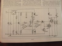
Here is a circuit that can do as well what you need, i took it from an elektor magazine. This circuit was made for soft start of 24V projector lighbulbs, but can easy be used for other things. It works with PWM.
Saved for later reference.
What Op amp was used?
Regards
M. Gregg
I have to admit that I do not see quite clearly what your problem was, and how you solved it... I understand it has to do with a cap, but other than that I am lost.
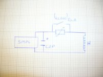
This quick sketch will make it simple to see..I just replaced the Cap with a simple filter circuit. As you can see when the NTC is low resistance it puts the heater across the Cap..which is OK if the system is not drawing to much current and then sits down in CL. Once the relay closes its locked out with a parallel heater cap load. Its such a simple circuit which is perhaps why I just didn't see the implications focusing on the series R and the NTC which worked until it was operated before it cooled down. Obviously the Relay has a timer circuit etc which is not shown.
So at first switch on the NTC is about 160 Ohms and the cap charges and the NTC heats and the current ramps up. The relay dumps the current from the cap into the heater and everything works..however if the system is restarted with the NTC in low resistance the cap struggles to charge against the current drain of the heater the next thing that happens is the smps is pulled into current limit trying to charge the Cap. This creates a point of balance that no matter what fixed resistor you try to use the heater either draws to much current and the cap fails to charge or the current is to low and the heaters stay in low resistance so when the relay operates the cap is drained and the smps goes back into CL..
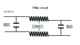
So I removed the cap and put the filter circuit between the SMPS and the soft start..to just help remove any HF ripple.
I would not have believed it could balance so well to create such problems..once the system works once you have to wait for some time to retry it because the tubes hold enough heat to offset the problem.
Regards
M. Gregg
Attachments
Last edited:
- Status
- This old topic is closed. If you want to reopen this topic, contact a moderator using the "Report Post" button.
- Home
- Amplifiers
- Solid State
- I would like a few ideas..