Here ya go. 68 watts at +- 35 V
http://www.national.com/ds/LM/LM3886.pdf
Beats anyting else you can build with 1-4 Transistors.
http://www.national.com/ds/LM/LM3886.pdf
Beats anyting else you can build with 1-4 Transistors.
Dear dorkus,
U have mentioned in one of ur email,
"incidentally, my Rega Brio uses a single 2955/3055 output pair and it sounds very nice, puts out about 35Wpc (at least 50Wpc in the custom version i built w/beefier power supply). but it also uses 3 other transistors for driver/bias and an opamp (TL072/AD711) for the input circuit."
i will like to have the total details about the said amp. It looks impressive.
Mahendra Palesha
hi palesha,
the Rega design is a very nice amp, very musical if done right. mine turned out a little bright but it is otherwise great - crystal clear with really lovely midrange/bass. it has stood up to "high-end" integrated amps up to about $2000, it is better than my friend's Krell integrated too. i will try to take some pictures of it for you to see... i do not have a schematic on me, i will see if i can dig one up somewhere.
dorkus
Attention
You must use an input stage for this schematic because this amp will act like a buffer!!!
this is what I found on the mentioned site:
best regards,
HB.
You must use an input stage for this schematic because this amp will act like a buffer!!!
this is what I found on the mentioned site:
An externally hosted image should be here but it was not working when we last tested it.
best regards,
HB.
most amplifiers excist of different stages:
most common:
1) input stage: differential amplifier: to allow feedback, balanced inputs, etc....
2) voltage amplifier stage
3) current amplifier stage (compare with a kind of buffer)
your schematic has only the third stage, so:
you need a voltage amplifier stage for this schematic, because your source (CD player, mixer, ...) has an output signal with an amplitude of ~1V and not 40V (like in the pictures).
HB.
tvi said:MJ amp
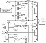
Now that looks like a nice simple little amp Some care has been taken in the Power Supply. What did they say about it?
Even thou i know little about SS circuitry i was a bit baffled with all the posts that said 4 transistors weren't enuff -- The incandescent Zen can be built with only 1 MOSFET.
dave
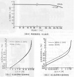
tvi said:Don't know, can't read Japanese, but here are the distrotion and frequency response graphs from the article.
Thanx. I also was wondering how this would work with lower rail voltages, say 25-0-25.
dave
Hello,
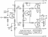
I have a question for the Japanese design. I don't see why one has to power a stage with mind-boggling 200V. It's using MOSFETs too. Not only that, the output stage is isolated by a pair of capacitors.
Is there magic in the MOSFET input stage? I see not much point in it.
I have seen another design refered to has "0-dB amp" among Japanese DIYers. (It's a solid state amp) It uses +-140V power supply. I am beginning to wonder what is the benefit of running BJT at such high voltage. Gotta be something but I dunno.
Tomo

Maybe it means 2sj162
2sj162 is supposed to be the complement of the 2sk1058. Those FETs have unusually low threshold voltages, so it looks like they'd probably work together in this circuit with the biasing scheme shown, although I'd probably want some adjustment, maybe a Vbe multiplier. Relying on LED forward voltages seems cheesy.
2sj162 is supposed to be the complement of the 2sk1058. Those FETs have unusually low threshold voltages, so it looks like they'd probably work together in this circuit with the biasing scheme shown, although I'd probably want some adjustment, maybe a Vbe multiplier. Relying on LED forward voltages seems cheesy.
Speaking of depletion mode
Although it is now getting a bit off topic, this might interest some folks:
http://member.nifty.ne.jp/MUTSU/e/hp005.htm
http://www.nei.com has the fets.
Not sure, but it appears that the complement of 2sj18 is 2sk60. But jeez they are expensive.
Although it is now getting a bit off topic, this might interest some folks:
http://member.nifty.ne.jp/MUTSU/e/hp005.htm
http://www.nei.com has the fets.
Not sure, but it appears that the complement of 2sj18 is 2sk60. But jeez they are expensive.
- Status
- This old topic is closed. If you want to reopen this topic, contact a moderator using the "Report Post" button.
- Home
- Amplifiers
- Solid State
- i want to build a amp with 1-4 Transistor MAX!! -very simple