It is easy to do better, with just a simple cathode follower. All we need here is a buffer. Refer to The Valve Wizard -Cathode Follower
Easy, why not show us then?It is easy to do better, with just a simple cathode follower. All we need here is a buffer.
Do you have an idea about the transconductance of this tube?
Why a 12AU7? There are better choices.
Hello
I have few 12AU7 and no other tubes.
Thank
Bye
Gaetan
Here they are:Hello
Could you post the asc file and the 12au7 model of your circuit ?
Attachments
Here they are:
Hello
Thank, hopefully you seen my post because I've deleted it by mistake.
Bye
Gaetan
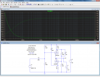
Note that U2 works with a slightly positive bias; this is because the valves operate with less than 50V Vak, which is really short.
However, this is not detrimental to the performances since U2 operates in a quasi stasis mode (except maybe for the input impedance): the THD remains below 0.007%
If you want to avoid that mode, you can reduce the string current, by increasing R1 for example.
But this will also increase the output impedance. Depends on where your priorities are.
Here they are:
I do not know how to plot output impedance with ohm-scale.
Can you assist a little ?
First, you have to plot a quantity expressed in ohm. The most obvious form is U/I, in this case the current and voltage from the stimulus source and the node of interest, but it can be a more complex mathematical expression (right-click on a trace name to enter it). LTspice makes a dimensional analysis and plots the result in the correct units.I do not know how to plot output impedance with ohm-scale.
Can you assist a little ?
Next, you have to change the left axis from decibel to linear: Plot settings --> Manual limits.
That's it
Hello Elvee
I finaly succeed to include your triode.lib into Ltspice to do the simulation of your vacbufecc82 circuit.
Now simulation are working.
Thank you
Bye
Gaetan
Are you able to plot the output impedance ?
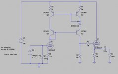
No function, no current, it just has to be the unique AC source on the sheet: make it AC = 1Thanks. I am closer to the solution.
How should the current generator I1 (=load) be configured ?
I have done it, but the results differs from the one achieved with traditional method,
i.e. using two different load resistances and calculating : (U1-U2)/(I2-I1) = Zout.
The result with your method is (@ 1kHz) 73,8 ohms and with the above method 55 ohms.
I make some other simulations.
i.e. using two different load resistances and calculating : (U1-U2)/(I2-I1) = Zout.
The result with your method is (@ 1kHz) 73,8 ohms and with the above method 55 ohms.
I make some other simulations.
- Status
- This old topic is closed. If you want to reopen this topic, contact a moderator using the "Report Post" button.
- Home
- Amplifiers
- Tubes / Valves
- I need a tube buffer circuit using a 12au7