Hi,
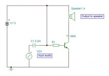
Shown is your amplifier redrawn.
As it stands it has a DC current through the loudspeaker, not good.
The DC current depends on R1 and transistor Beta and is temperature dependent, not good.
Added is how to measure it and how to AC couple the speaker.
rgds, sreten.
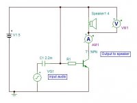
Shown is your amplifier redrawn.
As it stands it has a DC current through the loudspeaker, not good.
The DC current depends on R1 and transistor Beta and is temperature dependent, not good.
Added is how to measure it and how to AC couple the speaker.
rgds, sreten.
Attachments
Last edited:
start with some simple analysis of what is happening.I'm still confused .................. I hooked up the 12 volt power supply and it bumps my subwoofer showing at least half inch excursion it's insane everything in my house is vibrating like crazy
it's showing what looks like at LEAST 25-55 watts!!.........r...
If the available supply is 12Vdc, then the maximum AC voltage available to the load is +6Vk to -6Vpk. This is normally written as 12Vpp.
That 12Vpp is roughly equivalent to 4Vac. (12Vpp/2 = 6Vpk, 6Vpk/Sqrt[2] ~4.2Vac)
The maximum power, if your amplifier can actually deliver 4Vac, into your 8ohms speaker would be Pmax = Vac^2 / Rload = 4*4 / 8 = 2W.
Note, this is no where near your estimate of
at LEAST 25-55 watts.
Learn about what you are doing instead of grabbing at any silly notion that comes into mind.
Last edited:
wow... 4 watts pumping a 4ohm 12 inch 175 watt rms 500 watt max subwoofer.... at half an inch excursion?
yes my subwoofer is 4 ohms..
I say...
and yeah I seriously need to get rid of the DC going to the output! Ouch!!! It's not good for my speaker or the amplifier!
I think a good audio transformer would be the way to go.
but that's just my opinion.
If you want you can post a schematic of how I could get rid of the DC from my current circuit and make it better.
or a point to point wire to wire diagram would be helpful also... as I'm still not that good with schematics that much..
but an audio transformer would work wonders just by itself..
Last edited:
wow... 4 watts pumping a 4ohm 12 inch 175 watt rms 500 watt max subwoofer.... at half an inch excursion?
If the speaker is just in free space and not in a cabinet then you would see a lot of cone movement due to there being no "air pressure" for it to push back on. Thats part of what mounting speakers in a box does
")
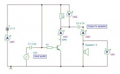
I doubt you'll come up with a suitable transformer. Did you try the AC coupled version I posted earlier. It will work but you need the correct value resistors.
My subwoofer is definitally in a subwoofer box
huge 2 and a half inch port on it major bass! still get half inch excursion never taken it out of the box since I put it in.
and sorry I have no clue how to AC couple my amplifier or whatever that is..
if I try using a capacitor in series with my subwoofer I get absolutely nothing at all
all I get is some tiny faint swishing pulsing sound that has no use.
My subwoofer is definitally in a subwoofer box
huge 2 and a half inch port on it major bass! still get half inch excursion never taken it out of the box since I put it in.
and sorry I have no clue how to AC couple my amplifier or whatever that is..
if I try using a capacitor in series with my subwoofer I get absolutely nothing at all
all I get is some tiny faint swishing pulsing sound that has no use.
As I keep saying, it's all in post #22 on how to AC couple the speaker. You would need a 6 ohm or thereabouts resistor and an assortment of resistors to get the base bias correct.
Your speaker cone moves 1/2" purely because of the DC current. It either pulls or pushes the cone depending on polarity. If the same voltage were an AC equivalent (its RMS value) and a low frequency sine wave then above some frequency determined by the speaker and its box you would find the cone movement much less.
no my speaker moves from the sinewave bass frequencies! I can totally see it and I can feel it in the walls of my house too.
the speaker pops out just slightly when I plug it in but that's only that... when I play music my speaker moves a LOT more whenever I play a bass heavy song
It easily moves half an inch from the bass frequencies alone. maybe I should just upload a video and put a link showing my subwoofer moving from the bass frequency sinewaves so you know im not faking it or something....
it's real! i'm not joking my subwoofer really moves this much!
and I still get amazing sound quality too. it only moves a lot when I have the 12 volt power supply hooked up..
when I hook the 5 volt power supply its about half as much but still pretty loud and clear and it doesn't get hot with the 5 volt power supply.
I believe it moves a lot like you say
Its surprising how little power you need at home, and if you haven't already seen it,
http://www.diyaudio.com/forums/mult...much-voltage-power-do-your-speakers-need.html
Its surprising how little power you need at home, and if you haven't already seen it,
http://www.diyaudio.com/forums/mult...much-voltage-power-do-your-speakers-need.html
and sorry I have no clue how to AC couple my amplifier or whatever that is..
Hi,
Is in post #22 and #41 in as plain point to point as you could wish.
rgds, sreten.
Please stop pretending your circuit actually works properly or does anything useful.
It doesn't, and you won't learn anything pretending it does. Reality is reality and bites.
Last edited:
Ah, the old subjectivist-objectivist debate again...Please stop pretending your circuit actually works properly or does anything useful.
i'm wondering if there's some way I could increase the watts going to my amplifier... to get louder sound.
how would I do that without changing the power supply?
a capacitor a transformer and a DC to AC converter or something?
not the ones for 12 volts i'm talking about something that simply generates a pulse from on to off so I can get AC from the power supply
then the capacitor will remove the background noise and change the AC to DC that is coming to the speaker so it doesn't make a hissing sound or buzzing sound
then will I somehow get more watts?
or am I wasting my time asking this question?
Hi,
Your wasting your time asking questions you don't understand the answers to.
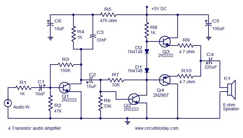
Loads of info here : Transistor
The next step is two transistors with feedback to set gain :
A = (R4 + R5) / R4
But your still a long way from an efficient power amplifier that will
make the most of of a limited supply voltage or using bridged.
rgds, sreten.
Your wasting your time asking questions you don't understand the answers to.
Loads of info here : Transistor
The next step is two transistors with feedback to set gain :
An externally hosted image should be here but it was not working when we last tested it.
A = (R4 + R5) / R4
But your still a long way from an efficient power amplifier that will
make the most of of a limited supply voltage or using bridged.
rgds, sreten.
Last edited:
I don't have enough resistors that are the correct values to make it like that
I only have one resistor that works perfectly the way it is.. maybe I should just get a transformer or something
also I'm only 15 years old and i'm home schooled at www.k12.com and I don't know hardly anything about electronics except how to wire something together to make it work... I don't know how to read a wiring diagram unless it shows exactly where every wire goes to the correct end of the correct component and which end of each component goes to the correct end of the other component..
I have no clue how to read a diagram if it doesn't state exactly which positive or negative or where which positive or negative wire goes where.
it's not like I can just look at it and guess which wire goes where.. I wouldn't even know where to hook the output positive and negatives to. or even where they are in the diagram..
I would need an image taken from a camera with labels showing which end of each wire is positive or negative and where it goes to which other end of the other component
then I could just make it look the same already knowing which end of my components are positive or negative and connect it the same way as the picture.
and if everyone is just going to hate on me just because I don't know something that you think is simple then I might as well have never asked in the first place.
Last edited:
................and if everyone is just going to hate on me just because I don't know something that you think is simple then I might as well have never asked in the first place.
Everybody on here started off by knowing zero about the subject. In fact I remember my very (very very) first attempts at electronics. Canibalising a little 6 transistor radio for all the parts and trying to cobble an amplifier together. Identifying transistor connections was a problem because I didn't know how to do it. And those arrows on the emitter (why did some point in and some out). I remember building a headphone amp using a single AD149 which seemed to need at least 20 volts to work... and understanding biasing... whats that.
But... I wanted to learn though and in fact learnt very quickly by my mistakes and by reading all I could get my hands on. And thats something we all hope you will do if you are interested. With todays technology a saying of my old boss comes to mind... "you've never had it so good". I used to cycle 40 miles round trip to a component wholesaler for a few BC107's or some resistors and caps. Always getting all the books I could from libraries and so on.
You have more help and people willing to help on a forum like this than you probably imagine... but you have to help yourself too
- Status
- This old topic is closed. If you want to reopen this topic, contact a moderator using the "Report Post" button.
- Home
- Amplifiers
- Solid State
- I just designed an amplifier to power big speakers with small voltage!