cunningham said:350W RMS /4R is only 53Vpeak. 70-53=17V. Assuming the supply rail doesn't drop much under load, Vce min of 17V is acceptable for most devices.
That's a tough assumption to make. Capacitor-input supplies are quite sensitive to transformer secondary resistance since the caps are charged by narrow high current pulses, which means the transformer outputs will tend to droop from IR lossage. Capacitance beyond a surprisingly small value doesn't much affect supply voltage.
Run some sims and see; the results may surprise you. This isn't only sim-based, by the way; real-world power amps also show this characteristic. For example, an amp I know quite well puts out 450 W into 4 ohms, implying supply rails of +- 60 volts, yet the unloaded supply runs about +- 80 V. The transformer isn't a dinky thing either; it weighs about 25 to 30 pounds.
Cheers,
Francois.
BIG TRANSFORMER PERSPECTIVE
Transformer sizes are not that important, the size in kVa is
the loooooong term average max output power. The interesting
thing is the winding resistance and the leakage inductance.
Toroids are in this perspective far superior to conventional
EI or UI transformers. Do also take look at what comes before
the transformer if you are looking at regulation. Especially in
the US and other places with childfriendly voltages in the wall
sockets. What is the average area that comes from the transformer station into your house and what area has the
cable running from the fuse box to the wall socket and what
lengths are involved. Can't the US citizens get a decent voltage like 235V from some special socket there must be possible how
do you feed welder and bigger machinery, I mean if you need something like 10kW you need 86A that means horrid areas of
the cables.
Returning to transformers, since the magnetic flow is undependent of loadcurrent the only thing that limits the possible power is the heating in the windings. In a toroid the winding length in a comparable sized tranformer is one third compared to an EI transformer. Together with lower leakage inductance this gives a far better regulation. Especially if compared to EIs with different winding compartments, these are really swampy but safe in the perspective of short from primary to secondary.
All in all, I have never heard of any poweramp with a burnt out powertransformer where the rest of the amp is OK.
I built a power amp for Gauss 18" 4ohm units, these *******s where really hard to drive max impedance 5ohm min 3.2ohm.
The poweramp had 6 Mj15023/4 in parallell in each channel.
80000uf and a 1kVA toroid. At full power the power lines dropped
less than a volt, and our guts where thrashed. What an experience, these speakers made waves in a glass of beer.
Ohhhh memories.
Those were the days of wooden ships and iron men.
Nowadays I go for switching, I am soon ready with a supply
with PFC, 2 kW 250x100x60 mm and weighing less than 1kg.
Component cost is comparable to a big conventional tranformer, and regulation is a completely different ballgame. An other good thing is that if things come to the worst, at a short a big transformer puts out currents that burns out PCB and other nice things, leaving an uncomparable mess. Short cirquit detection in a switching supply is immediate and reacts in a few us leaving traces etc unaffected.
Andreas W
Re: BIG TRANSFORMER PERSPECTIVE
Even non-citizens can get 220 VAC in their houses over here, as long as they pay their electric bills.
Andreas W said:Can't the US citizens get a decent voltage like 235V from some special socket there must be possible how
do you feed welder and bigger machinery, I mean if you need something like 10kW you need 86A that means horrid areas of
the cables.
Even non-citizens can get 220 VAC in their houses over here, as long as they pay their electric bills.

when we are talking "fractions of a farad" capacitance you should consider active current limiting at "power on" -- Sorensen does this in their big power supplies by placing a resistor in the primary path. A 10 ohm resistor will limit the current flow to 10 amps for a 110 VAC line. After a few seconds a relay shorts the resistor.
I have a 36,000 uF bank in the amplifier test bed -- it was quite easy to blow the diodes if the amp wasn't sequenced just right.
ESP has a schematic on his site. http://sound.westhost.com/project39.htm
Mine is a bit different, but accomplishes the same thing.
I have a 36,000 uF bank in the amplifier test bed -- it was quite easy to blow the diodes if the amp wasn't sequenced just right.
ESP has a schematic on his site. http://sound.westhost.com/project39.htm
Mine is a bit different, but accomplishes the same thing.
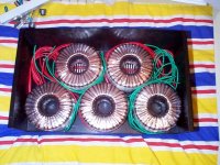
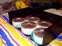
hmm.. yeah... maybe I should build the amp and powersupply seperate... that case is really too small... only problem is there are no more cases like that for sale... 
cos there's nooo wayyy I'll fit a soft start circuit in that case as well
my idea was to switch the transformers on seperatly... centre 3, then outer 2 like 3 seconds later..... shouldn't matter if the amp starts up with lower rails...
cos there's nooo wayyy I'll fit a soft start circuit in that case as well
my idea was to switch the transformers on seperatly... centre 3, then outer 2 like 3 seconds later..... shouldn't matter if the amp starts up with lower rails...
How about a triac controlled phase-sweep soft start? This gets rid of both transformer saturation at startup and controls capacitor charging current. It may be implemented as a small control PCB and a 25A triac using the case as a heatsink
One or more NTC thermistors in series and relay in paralell with them is also an alternative that gets rid of the big resistors usually required
See http://www.diyaudio.com/forums/showthread.php?postid=497160#post497160
I'm still experimenting but I think that selecting a triac with a holding current substantially higher than the magnetizing current of the transformers may allow for active DC filtering and noiseless operation of the transformers by means of some dead time added within each mains cycle
Eva said:How about a triac controlled phase-sweep soft start? This gets rid of both transformer saturation at startup and controls capacitor charging current. It may be implemented as a small control PCB and a 25A triac using the case as a heatsink
When you use Triacs you have to go to extra trouble to make
certain that the turn on timing is very symmetric, otherwise you
get some net DC and that will Really give you some
transformer saturation. IMHO, not worth it.
in regards to the above comment that a lot of capacitance can cause issues when turning on...
my recently completed aleph3's dont have this problem. i have 208,000uf per channel (416,000uf total for both), and they are on 12v triggers. they are turned on by my receiver. all three are turned on at the SAME time, and i just get a small dim in the lights. only have a thermistor on there, and that's it.
my recently completed aleph3's dont have this problem. i have 208,000uf per channel (416,000uf total for both), and they are on 12v triggers. they are turned on by my receiver. all three are turned on at the SAME time, and i just get a small dim in the lights. only have a thermistor on there, and that's it.
There is soo much fog in the starting up powersupply world. A transformer does not have a remarked start current. It will not satuarate unless connected to a much higher input voltage +20% or so. Since it is mainly inductive its own loading current is ZERO at the connection moment. U/L = di/dt (Remeber that ?) What causes the inrush current is the transformers load, a lot of C.
One can easily calculate the energy by E(J)=½ U x U x C.
If for instance we have +/- 40V and total caps 100000uf, the energy in caps is ½ x 40 x40 x 0.1 = 80J or 80Ws.
This is the energy that keeps a 80 W bulb alight for 1 second, not so impressing. Depending on stiffness of the transformer one could have to address this problem. A NTC resistor in the cirquit is not such an easy solution, since it has to maintain a high temperature as to keep the low resistance. Hot components are cumbersome, since their solders oxidize over the time etc.
I think the easiest solution is, get a hefty power breaker and let the lamps blink a little, that could be decorative. If the powerfuses blow, get bigger ones.
Andreas
Andreas W said:This is the energy that keeps a 80 W bulb alight for 1 second, not so impressing.
Well, keep in mind that the time in question is measured in 1/100s of a second, If the caps were charged in 1/10th of a second (10 rectified current peaks), it could light an 800W bulb in that time.
Now think of the peak currents in your rectifier bridges. The caps don't like this charging either.
If your circuit breakers on the primatry side blow, don't just get bigger ones. Start thinking of the current this results in on the secondary side.
My solution is to use a power resistor maybe 22 - 47 ohm) in series with the primary. When the operatingh voltage on the secondary is reached, make a relay short out this primary side resistor. Your PSU components will live longer this way.
Jennice
I'm not aware of such asymmetric triggering isues since the zero crossing detection is performed on a rectified waveform thus it's inherently symmetric
Also, the inductive and non linear behavior of a transformer with a rectified DC load requires permanent triggering after soft starting
But I'm aware of what happens to my plugs and switches when I don't use soft starting
Also, the inductive and non linear behavior of a transformer with a rectified DC load requires permanent triggering after soft starting
But I'm aware of what happens to my plugs and switches when I don't use soft starting
An externally hosted image should be here but it was not working when we last tested it.
Andreas_W :
A transformer has 50% probabilities of suffering severe saturation and working as if there were no core [primary resistance connected to mains] for several mains cycles when you plug it [with or without load]. The worst cases happen when the angle of the mains waveform is betweem 135º and 225º or between 315º and 45º at the instant of pluging it
This happens because the magnetic flux of the core lags 90º in respect to mains waveform and the primary turn count is chosen by manufacturers to use the full negative to positive flux swing allowed by the core at the rated primary voltage [2*Bmax peak to peak]
The flux takes its maximum positive value at 180º and its minimum negative value at 360º, and its zero crossing points are 90º and 270º. The flux is nearly 0 when you plug the transformer [some sources claim residual magnetization depending on the angle of the last power-off]
So figure yourself what happens with the flux when you plug the transformer at 0º or 180º, being the real flux 0 and the expected flux -Bmax or +Bmax
[Tip : The flux will try to travel to double its maximum value and the core will saturate for some time. The lower the primary resistance, the more noticeable the effect]
PD: And I don't like to see my computer or my oscilloscope resetting due to these mains brownouts
Fiat lux.
Transformers are more misunderstood than I thought was possible. I have noticed a gap in knowledge between what is tought at the university courses and the real world since I have been in booth.
First of all how on earth would it be possible ton connect these huge power transformers that supply our towns and industries with power if they had these huge starting currents?
Secondly since the Lentz law of induction:
U=N dQ/dt Q is the magnetic flow in the core.
N number of turns
Split it and integrate.
§ Udt = § N dQ
Ut = NQ
You will have the simple solution that the
integrate of voltage equals the maximum magnetic flow.
Since you don't have a full halfperiod at start up, the maximum needed flow is less than under normal operaion. Saturation of core can ONLY happen if you lower the frequency (more t) or have a higher voltage (more U). N is of course fixed.
On to the problem !
The real problem is charging the capacitors, this is the real problem.
Since
U/C= dI/dt
To charge a capacitor takes a lot of current if done very fast. To lessen this current an inductor in series or resistor helps, but that also makes the inner resistance in the powersupply higher.
But that is not desirable in our community.
The diodes in the rectifier bridges are made to cope with these inrush currents. So no problem there. There is only two real solutions.
One. Get a relay and a resistor in the primary. A delay cirquit closes the relay after a few period when the caps are charged.
Make certain that the relay doesn't open under any condition causing the resistor to be blown.
Two. Let the currents flow. Get a good industrial grade cirquit breaker, these can take current surges. Don't forget that other things like motors in fridges and other home appliances also have heavy start up currents. If your scope or computer resets by little dips there must be something wrong with them. I have several and never noticed any misbehaves from them during start up of huge electric motors, I am also into carpenting and use several big machines. Never any problem there.
The nice plug shown in the photograph, is not a cirquit breaker. I have seen several of those that have been on appliances without start currents. Plugs are NOT intended as cirquit breakers, since the making of contact is unreliable and slow. There must be some spring action as to ensure a rapid closing of cirquit.
This might seem as a petty subject, but I insist upon having every thing clear and proven. Otherwise you will end up in chaos. Once you have everything right, then you can move on forward. This is what they teach you in mathematics at universities, and their philosophy is applicable in a lot of other subjects as well.
Andreas
Andreas W said:Fiat lux.
One. Get a relay and a resistor in the primary. A delay cirquit closes the relay after a few period when the caps are charged.
Make certain that the relay doesn't open under any condition causing the resistor to be blown.
/B]
lux vita et vita nostra
what I am really wondering is how you made the "integral" symbols ? I guess I am not sufficiently webbified.
the appearance of a "short" to the diodes, which requires a resistor/relay combination, can last some milliseconds -- if there is no load on the power supply.
You still get inrush current with no caps connected.
With a transformer switched on at the zero-crossing of the voltage the magnetising current *also* starts at zero =instead= of negative maximum like in a running transformer. The mag current will hit now it's normal peak value at the peak of the voltage waveform, but the waveform still has a further 90 deg to go before it gets back to zero. This give the mag current enough time to go off the planet because the core will saturate.
As proof, try running a decent size tranny with nothing connected to the secondary. Every now and then depending exactly where in the AC waveform you switch it on, it will go *Bong!* and the lights will flicker.
Yep. With a *running* transformer as the voltage goes through zero-crossing and is positive for the next 180 degrees, the magnetising current (which is lagging close to 90 deg) goes sinusoidally from negative maximum, through zero to positive maximum.Eva said:The flux takes its maximum positive value at 180� and its minimum negative value at 360�, and its zero crossing points are 90� and 270�. The flux is nearly 0 when you plug the transformer [some sources claim residual magnetization depending on the angle of the last power-off]
So figure yourself what happens with the flux when you plug the transformer at 0� or 180�, being the real flux 0 and the expected flux -Bmax or +Bmax
With a transformer switched on at the zero-crossing of the voltage the magnetising current *also* starts at zero =instead= of negative maximum like in a running transformer. The mag current will hit now it's normal peak value at the peak of the voltage waveform, but the waveform still has a further 90 deg to go before it gets back to zero. This give the mag current enough time to go off the planet because the core will saturate.
As proof, try running a decent size tranny with nothing connected to the secondary. Every now and then depending exactly where in the AC waveform you switch it on, it will go *Bong!* and the lights will flicker.
Be cool, say it with integrals...
Starting from :
§ Udt = § N dQ
But for a sinusoidal supply Udt is actually :
U*sin(2*pi*t/T)dt
Being T the period and U the voltage amplitude
§ U*sin(2*pi*t/T)dt = § N dQ
Assuming N is a constant :
U * §sin(2*pi*t/T)dt = N § dQ
U * §sin(2*pi*t/T)dt = N * Q
So the flux is :
Q = (U/N) * §sin(2*pi*t/T)dt
Q = (U/N) * (-T/(2*pi)) * cos (2*pi*t/T)
So the flux amplitude is :
Qampl = (U/N) * T/(2*pi)
Qampl = U/(2*pi*f*N)
But this is only valid for steady state conditions. Now, the funny part is to see what happens with magnetic flux when you evaluate the integrals between particular phase angles and starting with Q=0
For example, let's plug the transformer at phase angle 0 with initial Q=0 and calculate the value of Q at 180º
Q[t=T/2] = initial_Q + Q[t=0,t=T/2]
[integration between discrete points]
Q[T/2] = 0 + (U/N) * (-T/(2*pi)) * ( cos (2*pi*(T/2)/T) - cos (2*pi*0/T) )
Q[T/2] = (U/N) * (-T/(2*pi)) * ( cos (pi) - cos (0) )
Q[T/2] = (U/N) * (-T/(2*pi)) * ( - 2 )
Q[T/2] = (U/N) * T/(2*pi) * 2
So starting from 0 degrees and Q=0, we have reached at 180 degrees double the steady state flux amplitude....
And the core has saturated since no tranformer manufacturer makes provision to operate their transformers at double the rated primary voltage or half the rated primary frequency [ie: provision for double the required flux amplitude at the expense of getting half the VA rating obtainable for that mass of copper]
SkinnyBoy said:hmm.. yeah... maybe I should build the amp and powersupply seperate... that case is really too small... only problem is there are no more cases like that for sale...
cos there's nooo wayyy I'll fit a soft start circuit in that case as well
my idea was to switch the transformers on seperatly... centre 3, then outer 2 like 3 seconds later..... shouldn't matter if the amp starts up with lower rails...
Hi Skinny,
I'd definitely be looking at a separate case for the amp. With that many transformers sitting under your amp, I think the chances are that you will pick up at least a little bit of radiated noise.... (and probably a lot).
Once you put your power supply in as well (I'm assuming at least 5 rectifiers and 5 banks of filter caps) I don't see where the room would be for your amps anyway
Tony.

- Status
- This old topic is closed. If you want to reopen this topic, contact a moderator using the "Report Post" button.
- Home
- Amplifiers
- Solid State
- I have +-50volt rails @ 1000VA, 37600uF per rail: what would you reccomend?