its so good to read things like this , there is much between the lines and I feel happy to be there. I remembered my first amp blow ") up, my sadness and helpful members.
up, my sadness and helpful members.
I hope everything will be solved and finaly it will be even much more fun. harder achieved goals is more joyfull.
up, my sadness and helpful members. I hope everything will be solved and finaly it will be even much more fun. harder achieved goals is more joyfull.
Fingers crossed for when I apply power for the first time.
hi bryantramos79,
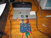
Well I set up the bias according to Carlos's instructions here:
DX Amplifier Adjusting the bias, and trimming DC offset
Everything went to plan. BIAS set OK in the correct range, DC offset also adjusted OK. No smell, no burning.
Time to remove the 10 ohm setup resistors and test at full power with the fuses in. Again no smoke. Measured temperature of devices, all OK. Check DC offset again, still OK.
OK let's plug in a source and a test speaker. Power on.... yeah music !!
First tune from this amp "One less bell to answer - The 5th Dimension". Next, "Hell's bells - AC/DC". Left it on for half an hour so far, all transistors are slightly warm at about 30 to 35 degrees C. Heatsink just warm at 22 degrees C.
So it turns out the only problem was using the BD140 that was supplied instead of a BD139 for the Vbias circuit shown on the DX website.
It looks like I need to stick it in a box and send it home.

regards
Attachments
Last edited:
Great news.
On the bright side at least the location of the original problem was self evident. On my latest project the SymAsym, one channel simply did not work, I spent hours looking for the issue having no idea where on this crowded pcb with lots of components the problem could be. I figured out that one of my Vbias transistors was connected backwards, but this was not causing the problem...so it took some helpful posts from others here to figure it out - a loose solder joint (invisible to my eyes).
I exploded a chipamp when it turned out that my plastic case was made of conductive plastic! I thought the screws holding the heatsinks into the plastic were insulated from each other but the plastic case actually connected a bunch of heatsinks (at different voltages) together. A LM4780 explodes with how do you say? A sharp report/ retort? Sounds like a .22 or slighltly larger gun being fired. Great fun when something THAT bad happens, and it was not hard to figure out what went wrong. It blew up the chip and also blew up that part of the board. You did better than me, your project is much more difficult than a chipamp.
People here will help you out, they have been helping me for years and I've got a bunch of working stuff. Someday you will be helping others so don't feel bad about accepting the help that is offered.
EDIT-on a side note, I did get a new 5 amp variac (120V) on EBay about 4 years ago for powering up my class A amps, I believe that it was not very expensive....I think less than $60. Someone sells these regularly, or did then. Its pretty large, and sturdy, from China but works fine.
Last edited:
Yikes.
That's gotta smart. A lot.
I know sod all about electronics, doesn't stop me though. Wait till you get hit by lumps of exploding power transistor
That's gotta smart. A lot.
I got mad when I blew a few outputs LONG ago on a repair. This can be expensive whether you do DIY or a repair. I knew enough even then to realize that the drivers were just a small amp by themselves.
One thing led to another and I refined this after 20 more consumer items. I just halve the main Re of the drivers (2 - 47R's for a 100R setup) temporarily tack these to the output bus and have a small working amp powered by the drivers.
I then adjust to 1.2v between P and N emitters , even listen to the amp with cheap headphones connected through a 22R resistor after I have determined there is no offset or magic smoke. Then.. and only then will I populate the main OP's , testing each one with the DMM as I go along. No more "crossing fingers".. I know at this point I will have no issues , even with 4 or 5 pairs hooked up as long as I check each one on a DMM and carefully observe polarity.
BTW , greg .. those 10R "screwup" resistors are my exact method.
OS
when I blew a few outputs LONG ago on a repair. This can be expensive whether you do DIY or a repair. I knew enough even then to realize that the drivers were just a small amp by themselves.One thing led to another and I refined this after 20 more consumer items. I just halve the main Re of the drivers (2 - 47R's for a 100R setup) temporarily tack these to the output bus and have a small working amp powered by the drivers.
I then adjust to 1.2v between P and N emitters , even listen to the amp with cheap headphones connected through a 22R resistor after I have determined there is no offset or magic smoke. Then.. and only then will I populate the main OP's , testing each one with the DMM as I go along. No more "crossing fingers".. I know at this point I will have no issues , even with 4 or 5 pairs hooked up as long as I check each one on a DMM and carefully observe polarity.
BTW , greg .. those 10R "screwup" resistors are my exact method.
OS
hey, I set fire to a 5 watt resistor in somebody's $4000 vintage luxman amp once...with the owner standing behind me...THAT was fun

- Status
- This old topic is closed. If you want to reopen this topic, contact a moderator using the "Report Post" button.
- Home
- Amplifiers
- Solid State
- I guess diy wasn't for me.