Hello all,
I have designed my first guitar amp. I thought I had a builder for it but he bowed out and recommended I find a willing soul on one of these forums.
I have a chassis in mind and just about all the details worked out.
It's an unusual design employing a variable gain circuit instead of the usual fixed gain and variable attenuation- I've found that turning things down is counterproductive- better just not to amplify them so much in the first place.
It is not a variation on one of the common manufactured amps.
I have a healthy respect for the hazards of high voltage and have never been able to manage a decent solder joint, so I won't be attempting the build myself.
I think this would be most interesting for somebody looking to do something a bit different.
anyone?
Ted
What technology does the amp use? Tubes, descrete transistors, opamps, other ICs, DSP processors? Does it need custom transformers? Are you going to supply all the parts?
An unknown design, with unknown technology and topology, with unknown expectations and no indications if the design actually works... I'll pass.
If soldering is not one of your strongpoints, are you capable of troubleshooting the amp once build? Just connecting some components together based on a 'new' schematic rarely turns them into a prefect working design on the first go.
Posting a schematic and maybe some pointers on what you expect from the builder (point to point, PCB, chassis work, component supply, etc.) might get more responses.
Edit: to be honest, soldering is not that hard. Loads of youtube clips on how to do it properly. So you might still give it a go yourself.
Last edited:
Introducing a variable resistor into the gain setting resistors is a BAD idea. If the pot has any high spots due to dust or wear, the gain might suddenly rocket to the maximum of that stage causing oscillation.
Nothing new about a variable gain stage. The Peavey Mace used it back in the late 70's and early 80's. Other Peavey models used the same solid state preamp with a tube power amp. There are many bass amps that use it today to prevent clipping of the first stage.
Nothing new about a variable gain stage. The Peavey Mace used it back in the late 70's and early 80's. Other Peavey models used the same solid state preamp with a tube power amp. There are many bass amps that use it today to prevent clipping of the first stage.
I agree , almost every overdrive/distortion pedal uses Variable gain and so do most mic preamps as well as a lot of SS guitar amps ....
Heck, the early Fender Tweed amps like the 5E3 with their reversed volume pot arrangement Were a kind of gain control. As you turned it down you loaded the cathode more reducing the gain of the stage. Not to say the OP is on the right track, looked up his previous posts and while his heart is in the right place I do not think he realizes you have to do a bit of real world fiddling when you wander off the beaten path. Not like you just draw up a schematic and all that is left is assembling the parts.
Ok, so it's an all tube amp. I'd be supplying the parts. Lundhal transformers. No IC's. I can get the chassis pre-cut and drilled.
I was looking at using an opto setup to vary the gain, but I've been warned that usually takes a lot of fiddling and tends to be unstable and unpredictable. So now I'm looking at switching the path between a couple options each for v1 and v2, giving a wide range of fixed gains.
This design uses a variac to scale the power section.
If anyone is actually interested I'd be happy to send them a schematic to peruse.
No, I'm not capable of troubleshooting it either. It'd be a matter of confirming that the voltages are as expected everywhere and tweaking resistor values to get the voltages where they ought to be, if they're not already.
Introducing a variable resistor into the gain setting resistors is a BAD idea. If the pot has any high spots due to dust or wear, the gain might suddenly rocket to the maximum of that stage causing oscillation.
Totally untrue. The most recent example is in the Douglas Self preamp.
"The volume control is of the active Baxandall type which gives low noise
at low volume settings........" Elektor 04-2012
I am fairly sure that no "rockets" are involved.
If a pot controls the gain, and an OPEN = max gain, then there is a danger of having the gain go to max without notice. All depends on which way the pot's position works and where it is in the circuit.
As far as using a variac to "scale" the power, you'd best take a close look at what is getting "scaled" WRT the required tube conditions.
Have you ever used or listened to a "scaled" power output stage?
A lot of folks do not like it much I am told.
Also, how do you know that the design will function?
Have you simulated it or otherwise engineered it?
Curious.
_-_-
Kevin O'Connor (member Struth here) discusses variable gain stages and adjustable power supplies in his TUT books. He even sells kits for some of his circuits. Find everthing here: Tube Guitar Amp Kits, Tube Amp Books - London Power
As far as using a variac to "scale" the power, you'd best take a close look at what is getting "scaled" WRT the required tube conditions.
Have you ever used or listened to a "scaled" power output stage?
A lot of folks do not like it much I am told.
Also, how do you know that the design will function?
Have you simulated it or otherwise engineered it?
Curious.
_-_-
I worked it out on paper with equations from the Valve Wizard books and Valve Amplifiers. Load lines, the usual simple power supply stuff. I suppose it's a "thought experiment" so far. It's really just minor variations on all the usual approaches. I'm just learning about the dynamics of the various factors, relating them to experience and some previous experiences having a friend do some minimalist mods on an amp he built that I bought, and making pretty conservative interpolations based on all that.
I had astonishing success coming from a place of complete intuitive ignorance and requesting mods from the aforementioned friend, a for real audio engineer of the old school. Sometimes he thought the ideas were quite crazy but we've worked together for a long time and he recognizes my uncannily high batting average as a musician meddling in technical affairs.
Now I know enough to be dangerous, and we'll see if my knack holds while integrating all this learning. My "experiments" with animated cabinets and motor mechanisms have been singularly successful as well. Another (couple) whole areas I have little but a musician's experience in, but things tend to work on the first try- usually quite a bit better than expected. But first lots and lots of ciphering, meditating, cogitating, and generally getting a feel for the dynamics and ideas.
I'd like to be doing totally radical unheard of things, but I only know enough about tube amps to do variations on the usual tricks.
I really appreciate the link to variable gain knowledge- I'll be pursuing that.
Thanks!
Ted
I haven't used a scaling amp before, but I've used an amp with relatively low voltages and liked it a lot- I found it very touch sensitive. I expect to find one or more sweet spots in the scale range and live there. It's also useful for me due to my off-grid life and a view towards portable off-grid applications. A little less power makes the batteries go a lot longer, and smaller lighter batteries too. This with an exceltech inverter or similar.
The scale sweet spot will of course have a lot to do with the interaction with the loudspeaker and cabinet. I can see how dropping below the happy zone for the speaker would be less than thrilling, and I would expect large amounts of attenuation to take a toll as well.
Off grid, eh?
Enviable position if you can make that work without making that your full time job.
So you are building a *battery powered tube amp*? Or, are you building a traditional tube amp that runs off an inverter driven by batteries?
Wondering what your major sources of power might be?
_-_-
Enviable position if you can make that work without making that your full time job.
So you are building a *battery powered tube amp*? Or, are you building a traditional tube amp that runs off an inverter driven by batteries?
Wondering what your major sources of power might be?
_-_-
Looks like the 'builder' will need to spend all his time on this. Basically it will be build , test and troubleshoot. It could be quite time consuming. How soon do you expect this project to be completed ?
Last edited:
I'd like to be doing totally radical unheard of things, but I only know enough about tube amps to do variations on the usual tricks.
I had a bright student drop out of my courses and go into electronic technology part due to his desire to design guitar amps and go where no man has gone before. I told him that when it comes to tube circuits you can pretty much bet someone has done it before. A couple of years latter after he graduated I ran into him and we talked guitar amp and he said I was right. Not to say you can not have fun discovering things yourself.
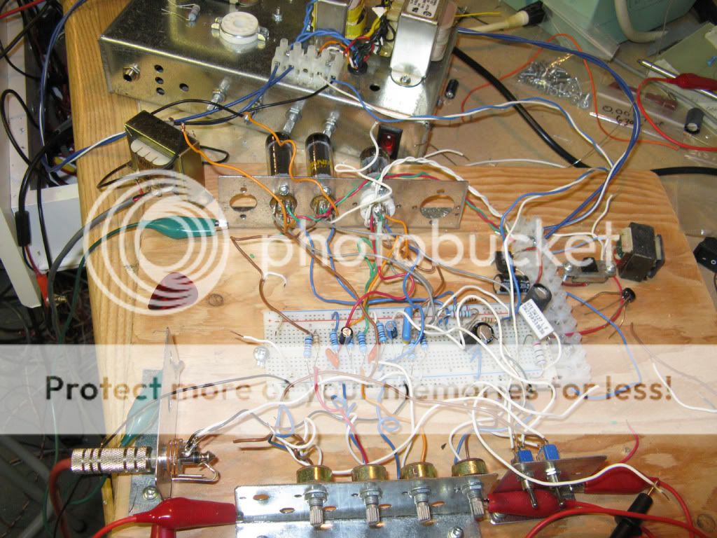
When it comes to guitar amps theory is a good thing but sometimes theory does not identify what sounds good. If you are not good at soldering make up a breadboard setup, Some people used rows of screw terminals, and wire up the circuits you want. I had a number of pots instead of resistors so I could vary them in real time and quickly determine what values work together sound wise. And yes I use an ordinary breadboard but I keep in mind the voltages when I decide how close a trace I use from another.
I'm curious why you are so hesitant to share the schematic? You can bet it's been done before, one way or the other. 'Getting radical' with a technic over a hundred years old, specially when inexperienced, is IMHO a bit naive. But posting the schem might convince a potential builder it has at least a chance of succeeding. Although I doubt it will at a first go. Schematics thought up on paper have the tendency to not work as expected, equations or no equations.
why not buy a few bucks worth of components and learn how to solder ???
Because it is addictive? 😉
- Status
- Not open for further replies.
- Home
- Live Sound
- Instruments and Amps
- I designed an amp- would anyone like to build it for me?