Here's what I can tell you:
1. Full range driver with helper woofers and tweeter all in the same box.
2. All drivers have outward motion when battery tested + terminal to +
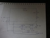
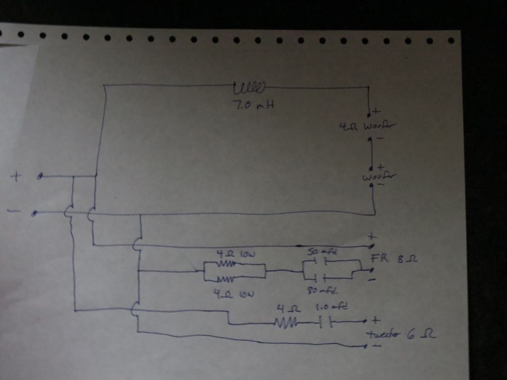
3. 6 dB XO (single coil on woofers, cap and resistors on FR.) 125 Hz.
4. XO components on FR are on the - terminal (not sure this is important)
5. Serious drop out near the XO point when all drivers connected + to +
6. No drop out when FR wired + to -.
What is going on here? I am glad I found it but I've not seen this before. Does it have something to do with driver interaction in the same box? I am confused.
Thanks for your input.
1. Full range driver with helper woofers and tweeter all in the same box.
2. All drivers have outward motion when battery tested + terminal to +
3. 6 dB XO (single coil on woofers, cap and resistors on FR.) 125 Hz.
4. XO components on FR are on the - terminal (not sure this is important)
5. Serious drop out near the XO point when all drivers connected + to +
6. No drop out when FR wired + to -.
What is going on here? I am glad I found it but I've not seen this before. Does it have something to do with driver interaction in the same box? I am confused.
Thanks for your input.
125 Hz.Wherabouts is the crossover point?
I have certainly heard the difference that 2nd order electrical or 180 out of phase does to the drivers and for the most part I like the reverse phase in that case, but I can't say I have experienced this with first order.First order will theoretically get you 90 degrees of phase difference at crossover. The drivers could then push it over the edge.
At the risk of sounding dumb, what does this mean?I assume your drivers are acoustically very close at 125Hz?
Have you by some chance reversed the XO??? I have done that once or three times
Me too but in this case, I have to deliberately reverse the FR to sort out the drop out.
A text book first order crossover should be flat with either polarity (not in reality though). This is because either way you'll have 90 degrees or -90 degrees (although lobing will be reversed).
When I said acoustically close, I meant compared to a wavelength. A quarter of a wavelength at your crossover is a couple of feet, so they are close (I was going to suggest a way of checking phase that only works if they aren't so close).
Your woofers do seem to be maybe a foot further from the listening position. The floor bounce image would come in at maybe another half a foot and the rear wall reflections would add some too. Due to the reflective surfaces and the side mounted woofers I'd think the reflections would be significant.
By the way, with corner placement at that distance it almost looks like you could have a phase reversal at the crossover point with the woofers.
I wonder if moving them closer to the walls would make an improvement to this lower crossover on all counts?
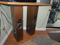
Cal somebody graffiti'd your drivers.Here is a pic of the speakers.
Ah, now I see. I missed the 125Hz in your first post and initially assumed you meant the FR to tweet crossover. Now I'm awake and see the pics, I'm with Allen, I suspect it's an attempt to tie in the side mounted drivers better with the mains.
Jerome, with the speakers positioned as they are, I don't think BSC is a major issue.")
Jerome, with the speakers positioned as they are, I don't think BSC is a major issue.
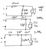
I think you can go further in the design of the crossover. It could not be your cup of tea, you could be shocked but you are in the multi way domain and it is interesting to listen other things. Flush mount the tweeter in this case. The crossover also works fine with a 6 ohms tweeter. See below
Yes the speakers are not in an ideal place. I think i finished now
Yes the speakers are not in an ideal place. I think i finished now
Attachments
Thanks to all for the explanations and suggestions.
Jerome, I must tell you the whole idea of these was to make use of the RS1354 driver that I know a lot of persons hold dear. I am trying to use as much of them and as little woofer and tweeter as possible. That's why the unusual values in the XO.
I also realize there is a little overlap between the side woofers and the FR and that the XO points are more like 150 and 175. I just guessed and used parts on hand. I have now looked them up. Only problem is I have no idea what the impedances are at the XO point. This is just a wing it project.
Yes, the placement of the speakers is not ideal. I have tried them in a number of locations, this just happens to the the resting spot for now. They have Holy Je*** bass where they are. Almost scary for a small speaker.
When I actually get these sorted out I will build a new cabinet with separate chambers for the FR and tweet. I was really just trying to get my head around why the FR's would need to be thrown out of phase in order to eliminate the drop out. The tweeters are on the same leads as the FR's so they were taken along for the ride when I reversed the FR's. The XO's are not board mounted yet.
Thanks again for your guys input.
When I actually get these sorted out I will build a new cabinet with separate chambers for the FR and tweet.

The full range speaker sharing the same chamber with the woofers are acting like a passive radiator below the acoustic crossover range, giving you Holy Je*** bass, and a phase inversion.Yes, the placement of the speakers is not ideal. I have tried them in a number of locations, this just happens to the the resting spot for now. They have Holy Je*** bass where they are. Almost scary for a small speaker.
When I actually get these sorted out I will build a new cabinet with separate chambers for the FR and tweet. I was really just trying to get my head around why the FR's would need to be thrown out of phase in order to eliminate the drop out. The tweeters are on the same leads as the FR's so they were taken along for the ride when I reversed the FR's. The XO's are not board mounted yet.
Run a sine wave tone through the cabinet around the Holy Je*** frequency, you will see the small cone acting like a PR, it will be at maximum excursion at the frequency where the woofers have the least excursion.
Persistence of vision with the graffitti cone will make it easy to see.
Because of the limited excursion of the full range, at louder levels the cabinet will revert to a sealed response for the woofers until the full range tears it's surround out, then it will have a 5" by 3/4" deep port
.Art
Hi Art, thanks. It is a ported cabinet but I agree about the PR effect as I have seen this in another project that was also ported. Silly me to have thought that being ported, there would be no effect as there wouldn't be a pressurizing of the cabinet. I now know that's not the case. This is why I wish to separate them in the 'real' cabinets. I will also raise them closer to ear level.
So this is causing a phase inversion is it? Very interesting. I wondered about that in my first post. I knew there had to be an explanation. Thanks for taking the time. Perhaps I will be running them in phase when they are separate?
So this is causing a phase inversion is it? Very interesting. I wondered about that in my first post. I knew there had to be an explanation. Thanks for taking the time. Perhaps I will be running them in phase when they are separate?
Run a sine wave tone through the cabinet around the Holy Je*** frequency
Actually, I think it's the corner loading and the shelf over top I am speaking of. They are fine when not placed where you see them. The reason they are there is I wanted to listen to the voices on the TV (wall mounted above the shelf) rather than just music. I find the spoken word is very telling when it comes to 'voicing' the speaker
- Status
- This old topic is closed. If you want to reopen this topic, contact a moderator using the "Report Post" button.
- Home
- Loudspeakers
- Multi-Way
- I am confused, I need your help