When you can explain the function and the value of each component, and make an estimate of performance (e.g. gain), then you are beginning to design. Later you may be able to suggest improvements.
I'm not quite sure what the point of this thread is.
Guy, I agree. It is of not good design to put transistors, tubes, resistors, trafos, etc . with no sense. It is really stupid.
The sense is to obtain ,of the schematic,is to otain an amp with the eficiency of the transistor and the sound of the tubes,i think is realy cool ideea,ho came up with it for the first time was a briliant guy,i promised to build it ,i dint' built it iet but i am going to keep my promise.
I think i have got to the final version 3db ateneution 1MHz.The schematic is based on the first one.
I have some dificulties with multisim i want to post the schematic but my os cant instal multisim i have linux(i have wine doors for windows app but it doesn work well) i wanted to give a try this os when i solve the problem i am going to post the schematic.
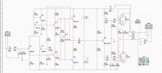
You maybe should check the grids of V3, V4 at the power-up of the +50V + 50V to make sure it is not getting too big a voltage spike, since the splitter Q6 comes up instantly. Oops, nevermind, I see it is configured +50 and -50 so should be OK at the center divider if they come up simultaneously.
The output transformer needs to handle the low audio frequencies, so ferrite core will probably not be appropriate (low Bmax).
Q9 has a drawing error I think. Q1,Q2 usually get some 100 Ohm, or so, emitter degeneration resistors. Q5 may need some small Miller comp. cap across collector to base.
The output transformer needs to handle the low audio frequencies, so ferrite core will probably not be appropriate (low Bmax).
Q9 has a drawing error I think. Q1,Q2 usually get some 100 Ohm, or so, emitter degeneration resistors. Q5 may need some small Miller comp. cap across collector to base.
Last edited:
I want to know much more about electroniccs but I cant learn it in one day,I just want smoethink to ask,can please somenone built the schematic the parts are not so expensive they can be found easaly ,2n5xxx and mje3xx I dont think they are a problem ,mje15032 can be replaced with a bd, the tranformer can be one within the tolerance of the valves that are going to be used.
can please somenone built the schematic
Hehehe that's very funny
 I think if you want to learn you can start with simulating and building proven schematics. It is more useful because you can see how/what a good amp should be made.
You can mix tube and solid state by using tube/ss preamp with ss/tube amp. But the usual convention for a hybrid is to use tube for the voltage gain, and ss for the current gain.
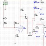
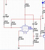
I made a tube input for my amplifier I will put it in practice tomorow the tubes that i am going to use are pcl82 I can wait to test it,first thing i need to do is to lower the voltage on my amp is bout +- 96 if somethink goes rong my speakers will pop.
Attachments
Yes, keep throwing components at it, maybe it will work...
PLEASE do yourself a favor and look into some of the most basic tube circuits until you understand how they work.
The funny thing i that tubes seem to be more simple than transistors,i will folow your advise.
- Status
- This old topic is closed. If you want to reopen this topic, contact a moderator using the "Report Post" button.
- Home
- Amplifiers
- Tubes / Valves
- Hybrid power amp