Ok, i have done as you suggested and with a 2K2 resistor on the output (had it lying around next to the amp) the voltages are as follows:
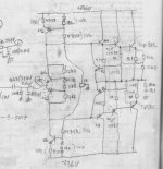
0) The rails measure at +33.91 / -33.89
1) Q2 = 800mV Q4 = 750mV
2) Q1 = 200mV Q5 = 150mV
3) 30mV
4) at the junction of R4 and R6 there is 17.27V and after R6 there is 720mV
5) at the junction of R8 and R7 there is 17.39V and after R8 there is 720mV
0) The rails measure at +33.91 / -33.89
1) Q2 = 800mV Q4 = 750mV
2) Q1 = 200mV Q5 = 150mV
3) 30mV
4) at the junction of R4 and R6 there is 17.27V and after R6 there is 720mV
5) at the junction of R8 and R7 there is 17.39V and after R8 there is 720mV
forgot to say.. theres 86mV accross R2 but nothing accross R1..
also the DC offset isnt there when i have the resistor load.. it returns when i plug the speaker back in but it seems to be much smaller (measured 700mV) that is with or without bootstrap caps in place.. so that seems to have fixed itself..
solid state and me obviously dont get on well..lol..
Owen
also the DC offset isnt there when i have the resistor load.. it returns when i plug the speaker back in but it seems to be much smaller (measured 700mV) that is with or without bootstrap caps in place.. so that seems to have fixed itself..
solid state and me obviously dont get on well..lol..
Owen
Hi Owen,
Hmmm
It seems by your voltage measurements that your output transistors are in cut-off. There should be like 600mV for Vbe on each device. Also you should see some voltage on R1 and R2. The voltage on these resistors should be the same(but opposite) when measured from the output node with no load.(33mV=100mA) and this may be plenty of bias. Q3 should have like 2.4V+2(VR1) Vce to account for 4 diode drops, or 4XVbe. R3 would be 1.2V+2(VR1). Bias currents can affect DC offset as the circuit(devices) is not perfectly symmetrical. This is the reason for GND references, and trim pot as mentioned by ilimzn in post #40. I would think that with a voltage divider of equal resistance, you would not have much DC offset though. A lot of circuits like this have a direct coupled front end with GNF that adjusts the DC offset. Will this circuit employ any GNF?
Bias: With the 4.7K at maximum on the Vbe multiplier(Q3), you should get no bias current as it is saturated. To turn it off(and bias on), SLOWLY decrease this value because it is possible to get too much bias so keep the voltmeter across R1,R2 to monitor this as you do not want to see much more than 50-60mV across either of these. Do this with no load, and then worry about DC offset.(like in post 40)
With AB emitter follower circuit, the DC load line(Vce vs Ic) is almost vertical depending on Re I have had circuits smoke because of crappy breadboards and the Vbe multiplier cut-off or came disconnected. I like to place a zener or diode string (5 diodes or 4 and 1 Ge diode) across Vce of multiplier(Q3 in your circuit) while using breadboards for protection.
Strange to see no DC accross the resistor but only accross the speaker...could it be occilating because of reactive loading??
I was thinking that placing a voltage regulator between Vcc and R4,R7 since they are bootstrapped might improve PSRR???? I'm not the expert at bootstrapping so maybe ilimzn can answer this.
PS I like the +/- CCS also, but with capacitor coupled input they would have to be quite acurately equal.
Anyway, G L here")
Hmmm
It seems by your voltage measurements that your output transistors are in cut-off. There should be like 600mV for Vbe on each device. Also you should see some voltage on R1 and R2. The voltage on these resistors should be the same(but opposite) when measured from the output node with no load.(33mV=100mA) and this may be plenty of bias. Q3 should have like 2.4V+2(VR1) Vce to account for 4 diode drops, or 4XVbe. R3 would be 1.2V+2(VR1). Bias currents can affect DC offset as the circuit(devices) is not perfectly symmetrical. This is the reason for GND references, and trim pot as mentioned by ilimzn in post #40. I would think that with a voltage divider of equal resistance, you would not have much DC offset though. A lot of circuits like this have a direct coupled front end with GNF that adjusts the DC offset.
Will this circuit employ any GNF?Bias: With the 4.7K at maximum on the Vbe multiplier(Q3), you should get no bias current as it is saturated. To turn it off(and bias on), SLOWLY decrease this value because it is possible to get too much bias so keep the voltmeter across R1,R2 to monitor this as you do not want to see much more than 50-60mV across either of these. Do this with no load, and then worry about DC offset.(like in post 40)
With AB emitter follower circuit, the DC load line(Vce vs Ic) is almost vertical depending on Re
I have had circuits smoke because of crappy breadboards and the Vbe multiplier cut-off or came disconnected. I like to place a zener or diode string (5 diodes or 4 and 1 Ge diode) across Vce of multiplier(Q3 in your circuit) while using breadboards for protection. Strange to see no DC accross the resistor but only accross the speaker...could it be occilating because of reactive loading??
I was thinking that placing a voltage regulator between Vcc and R4,R7 since they are bootstrapped might improve PSRR???? I'm not the expert at bootstrapping so maybe ilimzn can answer this.
PS I like the +/- CCS also, but with capacitor coupled input they would have to be quite acurately equal.
Anyway, G L here
I agree with the comments that suggest there is a basic error in the implementation of your circuit. From your latest schematic the output offset should be less than 100mV and should not change much with resistor or speaker loading.
The fact that you measured 86mV across R2 (indicating 260mA current flow) and nothing across R1 is bizarre. Where is the 260mA flowing?
The fact that the dc offset is 30mV with 2k2 but rises to 700mV with a speaker is bizarre too. This definitely smacks of oscillation. The trouble with oscillation is that it tends to throw off your multimeter measurements - dc values don't always read correctly when there is HF present.
I'd try some oscillation preventatives and then re-measure. First, put a zoble on the output - 10-ohms in series with 100nF to ground or thereabouts will do. Next, put a cap from "IN" to ground of about 1nF. Next, make sure your power rails are decoupled properly...10uF or more from the collectors of Q2 & Q4 to ground. Next, make sure your ground point is near the circuit and is in one place - a star point - otherwise the different currents in the different ground wires will causes voltage modulations and this can cause instability. If necessary, disconnect C4 and C5.
Try this and remeasure your dc voltages as before. Note that the voltage across R1 & R2 should be identical and somewhere between 20mV and 50mV (adjust using VR1). The base-emitter voltages of all transistors should be between 0.6V and 0.7V. The dc offset (loaded or not) should be less than 100mV.
This circuit design is fine. There are just some implementation funnies going on. All fixable. I assume all your transistors are in good shape or are new.
they are all new except the output transistors which i have some spares off so i'll test all the transistors and check the circuit for errors. And i will add the suggestions to helpp prevent oscilation. the circuit is useing star ground, there are only like 2 or 3 ground connections and they all split off directly from the ground wire comeing from the power supply and dont go into the breadboard atall, i will try and shorten these as much as possible and see if this helps..
Many thanks,
Owen
Many thanks,
Owen
OK, great!
Two possible problems:
1) check the polarity of your bootstrap caps
2) Oscillation
When you have eliminated 1) as a possible error, ground the SS input BEFORE the caps (at the junction of the two input caps that would normally go to the output of your tube front end). Then, recheck bias and offset.
If the offset and bias stays normal, then you actually have a fully working SS output stage, in fact, it's working so well, it's Av is so close to 1 it is oscillating. To cure this, for starters, you may want to try a Boucherot cell on the output - say a 10 ohm resistor (use one >1W) in series with say 0.1uF foil cap, then put the whole thing in parallel with the output. After you ahve done that, remove the short circuit on the input, but keep your hand on the power switch, if it is still oscillating, the 10 ohm resistor will go up in smoke!
Regarding your 40mV measurement, from whch lead of R1 and R2 (is it across one or two resistors?)
i have done as traderbam said and put a zoble network on teh output.. is that what you are refering too aswell?
I havent put the cap on the input.. or atleast i havent yet because i cant find a small enough cap in my parts boxes.. lol.
Cheers,
Owen
EDIT: forgot to say 40mV was accross the two resistors..
EDIT 2: also forgot to mention.. the caps i was useing in the bootstrap were non polar electrolytics.. should i be useingnormal electrolytics in these positions?
Owen
'd try some oscillation preventatives and then re-measure. First, put a zoble on the output - 10-ohms in series with 100nF to ground or thereabouts will do. Next, put a cap from "IN" to ground of about 1nF. Next, make sure your power rails are decoupled properly...10uF or more from the collectors of Q2 & Q4 to ground.
I havent put the cap on the input.. or atleast i havent yet because i cant find a small enough cap in my parts boxes.. lol.
Cheers,
Owen
EDIT: forgot to say 40mV was accross the two resistors..
EDIT 2: also forgot to mention.. the caps i was useing in the bootstrap were non polar electrolytics.. should i be useingnormal electrolytics in these positions?
Owen
Yes to Zobel... and it has these problems with the zobel on the output?
There may be many reasons for this circuit to oscilate, even long wires from PSU to your breadboard could be a problem.
Regarding caps, bnon-polar is fine, although you can use polarized (cap to +rail bootstrap has - conencted to output, cap to - rail bootstrap has + conencted to output). They have to be able to withstand at least 16V, preferably the whole rail voltage.
Hi Owen,
Did you install supply decoupling caps near the output transistors? Take that common junction to the supply via a separate wire. The zobel and speaker load return should also take a different route to your supply.
Once you have this running you can try bootstrapping and CCS. Remember that without an input load, the circuit may become unstable.
-Chris
ok.. the circuit is deffinatley oscilating.. BUT it seems to work fine if i keep my finger ont he ground connection.. so i am going to rewire all the ground connections and shorten the leads from the power supply and see if that halps the situaition.. so i should have seperate wires going back to the ground terminal on the power supply for the output transistor decoupling cap's and the zobel and speaker returns? how i have it at the moment is one wire from the power supply which then splits off into 4 wires.. one for speaker and zobel (on the same ground) one for decoupling caps on the output transistors and one for the input and one that was connected to the resistors on the input... I'll rewire all the power wireing and see if that helps.
Thanks,
Owen
so i should have seperate wires going back to the ground terminal on the power supply for the output transistor decoupling cap's and the zobel and speaker returns? how i have it at the moment is one wire from the power supply which then splits off into 4 wires.. one for speaker and zobel (on the same ground) one for decoupling caps on the output transistors and one for the input and one that was connected to the resistors on the input... I'll rewire all the power wireing and see if that helps. Thanks,
Owen
You are getting there!
On the ground wiring...find a point near the circuit to place the star (like within 20cm). I'd have 5 wires coming from the star point:
1) one to the psu ground
2) one to the zobel & spkr grounds
3) one to the + supply decoupling cap
4) one to the - supply decoupling cap
5) one to the input ground (where the 220k resistors and the 1nF cap are connected)
Try to keep the area enclosed by current loops small. So you might want to twist all the wires that go off to the psu together.
Get this working first before you consider going back to current sources on the input.
i found the problem.. i think.. I by chance decided to measure the 0.33Ohm resistors... One of them measures 1Ohm and the other measures open strange thoguh because they look fine and they wernt getting hot or anything :S but yeh.. i will try and replace them and see what happens.
I have shortened the power supply wireing and i have run all seperate ground wires now.. but i still have the same problem, it still only works properly if i keep my finger on one of the ground connections.. could this be to do with the 0.33Ohm resistors beign shot? they may not be shot, my multimeter might just not like measure such small resistors :S who knows.. lol
I dont have the 220K resisrtors in at the moment and i cant find any 1nF cap's in my parts bin so there isnt a 1nF cap in there either yet (will look more later)
Many thanks,
Owen
strange thoguh because they look fine and they wernt getting hot or anything :S but yeh.. i will try and replace them and see what happens. I have shortened the power supply wireing and i have run all seperate ground wires now.. but i still have the same problem, it still only works properly if i keep my finger on one of the ground connections.. could this be to do with the 0.33Ohm resistors beign shot? they may not be shot, my multimeter might just not like measure such small resistors :S who knows.. lol
I dont have the 220K resisrtors in at the moment and i cant find any 1nF cap's in my parts bin so there isnt a 1nF cap in there either yet (will look more later)
Many thanks,
Owen
Hi Owen,
Get all your grounds and bypasses set up first. You can use 220K to whatever you have lying around. I was going for about a 100K load to the tube section.
Try 2n2, 3n3, 4n7 ~100nF. The exact value is not very critical right now.
Your R33 resistors may have left the planet when you first powered this up in a burst of oscillation. You never know, so don't worry about it right now.
-Chris
Agreed!Get this working first before you consider going back to current sources on the input.
Get all your grounds and bypasses set up first. You can use 220K to whatever you have lying around. I was going for about a 100K load to the tube section.
Try 2n2, 3n3, 4n7 ~100nF. The exact value is not very critical right now.
Your R33 resistors may have left the planet when you first powered this up in a burst of oscillation. You never know, so don't worry about it right now.
-Chris
welll... i changed the 0.33Ohm and guess what! IT'S ALIVE!!! now it sounds rubbish at low volumes but REALLY sweet at max volume.. I cant measure any voltage accross the resistors now though so i dont know what the bias is doing.. but it is makleing a differance because as i turn it up the sound gets better!
It's always the same isnt it.. just as your about to give up you accidentally fix the problem and everything falls into place..lol
Many thanks,
Owen
It's always the same isnt it.. just as your about to give up you accidentally fix the problem and everything falls into place..lol
Many thanks,
Owen
Next on my list is to add the input cap and resistors AND a new zobel capacitor because i somehow managed to snap one of the legs of it just then but atleast its workiong now and produceing actuall music! it sounded like one of the output devices were fried earlier just like the last set of output devices i tried to use but YAY! hehehe
Owen
but atleast its workiong now and produceing actuall music! it sounded like one of the output devices were fried earlier just like the last set of output devices i tried to use but YAY! heheheOwen
Hi Owen,
Your outputs are on heatsinks now, correct? Just checking.
Try the sound at different bias levels. Start at 10 mA and up to 100 mA. Just measure the voltage across the R33 resistors. Watch the heatsink temperature at the higher bias levels. Above 50 mA make sure the bias will settle in and stay put.
-Chris
they have been on a heatsink from the start. they get ever so slightly warm to the touch ( and i mean ever so slightly warm) at the max bias i risked trying. I am haveing trouble getting my multimeter to recognise any voltage whatsoever accross the R33 resistors.. :S even accross both of them i cant get it to register any voltage..
I'm going to add the resistors ont he inputs and the input capacitor ( that should be before the two 2.2uF caps right?) and fix the zobel network befor ei play aroudn much more..
I tried adding the bootstrapping caps back in but the sound got worse.. so i took them out again... mabey i will experimant more with them later.
many thanks,
Owen
- Status
- This old topic is closed. If you want to reopen this topic, contact a moderator using the "Report Post" button.
- Home
- Amplifiers
- Solid State
- Hybrid amplifier.. Please help..