Hi
just test and see what it does, it do work nicely.
Now I go on with my own, otherwise I get time shortnesses. or who do I write this
regards
Really nice results !

only few remarks ,
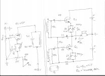
- R1 need to be around max 82R , and C2 around 680uF , in the same time Rfb trim pot R2 need to be with ten time smaller value(50R max or lower) since R2=500R@50% will be upset way to much optimum bias point of 6C45P tube , which is when DC voltage on cathode is around 2VDC or Ia ~30mA ,
and yes Rfb (R3)in that case need to be lowered to around 500R ,
-this few modification results in significant lowered impedance of current GNFB loop which is good effect ,
- R4 need to be around 56K max , with 470K 6C45P will oscillate somewhere in UHF band ,
- output coupling cap value need to be raised on let`s say 10KuF at least for really good bass spectrum response ,
all in all I think that we are now very close to one very good sounding A class amp
")
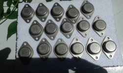
Sanken ring emmitors are extreme liniair, but do not now if she still be made, is used in expensve high end amps.
Why you do the idle system not from a center tappen transformer? because I did try use zemers fopr stabilization and it do not work wel on negative side, the sepp/ots itselfs with one supply do work.
regards
it is my opinion that quality N-type power BJT`s ( Sanken or ....) is good for straight in on this SEPP configuration but biased in (a)/B class , for pure A class operation with BJT`s some thermal compensation scheme must be involved ,
problem with zener bias generators when amp use bipolar PSU is that if you raise zener`s load resistors values to much than bias voltage source will be with to low values for correct OPS biasing ,
personally I will go without any zeners diodes , I will use only two bias resistor + two bias trim pot + (10R +1000uF) ,
how do you mean to made idle system just from center tap of transformer ?
 , please explain .
Last edited:
and one with a power penthode in it, jj has them, more distortion however most even harmonics like penthodes do..
regards
I think that 6l6GC is way too much powerful tube(overkill) for driver position in this simple hybrid amp , even triode strapped ,
maybe EL84 pentode(or 6V6) but triode strapped can be some acceptable solution , special in case if you intend to use some preamp unit .
Last edited:
Hi
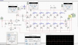
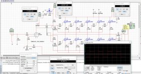
I have corrected all, it was because models are not always oke, but find a better one and these looks oke, have 17 mA with the resistors you mention, the feedback is changed, it is current feedback so low value is oke, until dissipation gets high, but with 500 ohm and 50 ohm it stays in borders, amp is not so high voltage, but has big current, so 2 ohm spekaers can also be connected?..
why is the big cap needed on tube? without it do also fine and little lower distortion, special in low frequenty part, the cap do make setup of idle in a slower way as sim let see, not a problem because you have cap in output.
the cap of 100 P on the transformer give in sim a ringing in negative square, without it do much better.
Did squares, these do nicely for a transformer. I have done measurements with a idel current of 2 amps for all fets.
regards
Attachments
I think that 6l6GC is way too much powerful tube(overkill) for driver position in this simple hybrid amp , even triode strapped ,
maybe EL84 pentode(or 6V6) but triode strapped can be some acceptable solution , special in case if you intend to use some preamp unit .
I did use these because I have nothing else, a eL84 is a good choise, these sound very well, special the phillips types.
Mine hybrid has a tube from EI, who west did bomb, so pity we have so little love for technology, glad I am here where it is full of them.
Hi
I have corrected all, it was because models are not always oke, but find a better one and these looks oke, have 17 mA with the resistors you mention, the feedback is changed, it is current feedback so low value is oke, until dissipation gets high, but with 500 ohm and 50 ohm it stays in borders, amp is not so high voltage, but has big current, so 2 ohm spekaers can also be connected?..
why is the big cap needed on tube? without it do also fine and little lower distortion, special in low frequenty part, the cap do make setup of idle in a slower way as sim let see, not a problem because you have cap in output.
the cap of 100 P on the transformer give in sim a ringing in negative square, without it do much better.
Did squares, these do nicely for a transformer. I have done measurements with a idel current of 2 amps for all fets.
regards
- Of course that nominal 2 ohms LS can be connected , special in case when we have SEPP-OPS which consist of 5 pairs of K1058 connected in parallel ,
- that cathode cap need to be there just to get maximum gain from 6C45P tube , without that cap tube driver distortion will go down because of local cathode NFb but the gain will go down to ,
- parallel 100pF cap is needed there against HF oscillation which very high gain (~52 ) 6C45P triode tube sometime have trend , but also introduce HF roll of,
any way you can try there with some smaller value cap as 82p or 68p but not less than 47p ,
-also I think that you can raise the SEPP-OPS idle current at let`s say 5A , and in that way to get more A class operation region ,that will introduce static dissipation per each K1058 device of around 29,5W which is OK SOA wise .
Last edited:
Hi
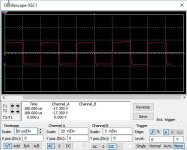
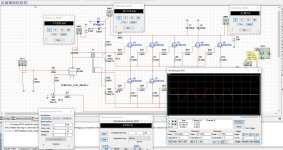
I have not a signal it do go lower in amplitude when remove the cap, it has a little more distortion when remove it.
these amp can sound nice, special because the harmonic content seems to even ones who are more present.
here some tests, and now I presume, you go build it and shake joegoslavia on his ground.
regards
Attachments
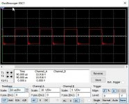
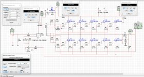
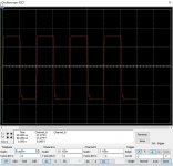
Oke some put extra, resistors over the transformer output damping ringing on HF, and need expermenting how big she need, sim is not 100 procent accurate.
cap is 150 pF, this do make 100 Khz square free of overshoot, this is not very good if we do nothing about it, making sound hars.
oke and I let you try it out, I have much work to do and go on with it, succes with building it.
regards
cap is 150 pF, this do make 100 Khz square free of overshoot, this is not very good if we do nothing about it, making sound hars.
oke and I let you try it out, I have much work to do and go on with it, succes with building it.
regards
Attachments
Kees52
- I guess that when we remove that cathode cap OLG goes down and GNFB become less effective and than THD factor goes up ,
-yes the specific output harmonics content is the thing which I hunt for here ,
- of course that I will build this hybrid A class amps ,
but no chance to shake to ground Yugoslavia with them ,since Yugoslavia is already shaked to ground and not exist any more , but will shake my loadspeakers for sure .
BTW
when you have time check schematic from my post #17 ,
where OPS is autobiased as vacuum tubes sometime is but now using SS- Ntyp SIT power devices ,
since I`m wonder how that amp will behave with pair of normally ON trench power N-JFET`s typ SJDP120R085 or typ SJDP120R045 ?
ps,now I have to go to repair some broken TV`s and to make some cash
Best Regards man !
Last edited:
Nope , I don`t have those sim models , but maybe someone from this site have something ?
edit , just found something for SJDP120R085
.subckt SJDP120R085 D G S\n.param R=530m ; R_gate\nBg G Gi I=-UpLim(47m*\n+ uRamp(V(D,Di))**3.5,10,1)/R\nRg G Gi {R} tc=-3m\nRd D Di 70m tc=4m 40u\nCsd S Di 3p\nCgd G Di 13p\nJi Di Gi S SJDP120R085\n.model SJDP120R085 njf\n+ Vto=-4 Beta=45 B=30m\n+ Lambda=500u Vk=2k5 Alpha=20u\n+ Is=1f N=3.4\n+ Isr=1n Nr=6.8\n+ Cgd=1n Cgs=610p Pb=2.6 M=0.92\n+ Kf=100f Af=1\n+ VtoTC=-2m4 BetaTCe=-0.65 Xti=86\n.ends SJDP120R085
Last edited:
Kees52
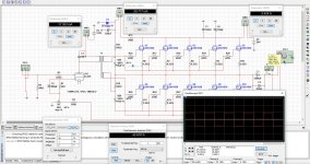
Here is the corrected schematic from my post #17 , so when you have time check it out with device SJDP120R085 ,
I believe that parameters model from my previous post is correct one .
Thanks again !
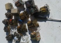
I see here are bipolairs? but some strange way of using them bu use a emittor degeneration pot of 20 watts?? and a ac path through two caps, it is a idea to fight run away, but I think there are better ways.
I go try the model, is it from infinion? because the other is gone, the 120R100 has need a negative 12 volts for conduction, this is better to control it then 1.5 volts negative, or positive as I had, needing very low idle resistors and beefy driver..
I have multisim, so need a model for it, but see that this one can work thanks.
Kees52
Those devices sign are not for BJT but for SIT transistor ,
easy way to get stable negative gate bias voltage in respect to source is auto bias scheme same as in by some vacuum tubes applications ,
but than some heat from W.W. source trim pots must be accepted for sure ,
but hey this is A class game here so heat from different sources and devices is one normal appearance ,
strange that SJDP120R085 sim model don`t work since it is sourced from one our DIY member.
big Thanks for your efforts&help !
edit , 20 for that source trim pot`s is 20 ohm , and W.W. mean Wire Wound not Watt`s
Last edited:
Kees52
Those devices sign are not for BJT but for SIT transistor ,
easy way to get stable negative gate bias voltage in respect to source is auto bias scheme same as in by some vacuum tubes applications ,
but than some heat from W.W. source trim pots must be accepted for sure ,
but hey this is A class game here so heat from different sources and devices is one normal appearance ,
strange that SJDP120R085 sim model don`t work since it is sourced from one our DIY member.
big Thanks for your efforts&help !
edit , 20 for that source trim pot`s is 20 ohm , and W.W. mean Wire Wound not Watt`s
I can seek the sic, yes I now it is a J-fet but on schematic you drawn bipolairs, as with tubes our mosfets, we talk about much more current here, I do not like so much that aproach making a heater of it.
But first I go on with X, between these work i help you out, I can change my model of the sic, making it other gate on voltages, so we can also come close.
regards
Hi Banat
I am very busy with my own allfet circlotron, and have not have the time to do other things, have work to.
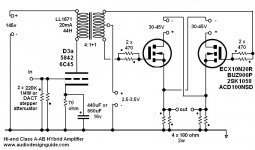
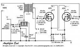
but I did see this schematic on the internet so you can see how other do, however get into account that there is a voltage on the transformer secondairy for the mosfet idle current maybe transformer get saturated.
regards
kees.
I am very busy with my own allfet circlotron, and have not have the time to do other things, have work to.
but I did see this schematic on the internet so you can see how other do, however get into account that there is a voltage on the transformer secondairy for the mosfet idle current maybe transformer get saturated.
regards
kees.
Attachments
Hi Kees
-Yes I have noticed that you are very busy with finishing your Alfet Circlotron project , which topic I always follow ,
-I know that hybrid schematic developed by Grant and followed by Audidesignguide , its OK , but as I have already say this time I want amp with SEPP-OPS not Circlotron- OPS,
-I know that interstage drive transformer is one very crirtical part for this type of amp , but with right IT transf. results can be very good .
-any way there is another options for simple hybrid amp which don`t use any IT transf. , but about that later ...
Regards !
- Status
- This old topic is closed. If you want to reopen this topic, contact a moderator using the "Report Post" button.
- Home
- Amplifiers
- Pass Labs
- Hybrid A-class retro amp