You are using the chassis as audio ground (non isolated RCA) or am I not seeing this correctly?
yes i guess i am
strip that out and start again.
The signal connection is a two wire connection.
You must have two wires running from RCA socket to your input stage.
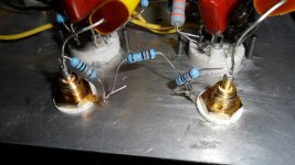
I can only see one ! Going to the capacitor.
Where is the other?
this is the output
yes i guess i am
i never used the chassis metal as ground returns for the psu power leads,
i use a dedicated wire for that, and twisting them were practical....
looking at your input rca jacks, there should only be a resistor shunting the
inputs, this resistor can be anywhere from 100k to 470k, these resistors
terminate your input jack, now for the jack outer shell, there should be a ground
wire that connects to the psu last cap negative lead...
i would like to see a wire each that runs to the last psu cap negative lead...
Ya agree, just happen to be another variation, it does change the bias resistance, it would affect bias if DC coupled. The builder is ChopChip, the sch is attached as post #1, he has vol pot in front I believe, ChopChip please you're ask to send a picture of actual build.
The problem is not uncommon, please read the forum for a similar problem Humming sound in stereo amplifier | All About Circuits
looking at the way he split the plate load resistors, could he be thinking balanced outputs?
my take is to replace that pot with a 470k resistor, then move that pot to input instead...
the last thing you'd want in any tube amp is to change operating points,
you change the signal input level, but you want the gains of stages fixed....
in my tube amp, all ground wires return to the psu last cap negative lead and
that point is the point that connects to chasis metal frame...single point star...
this worked for me all the time, my amps are quiet, no hum and no hiss...
at this point, carefull attention to flament wiring is also a must,
twisting the flament leads, grounding filament winding center tap or a vrtual center tap,
or lifting it with dc voltage bias, all these taken together helps...
and this last one takes care of the buzz...
once you learn these, then all your succeeding bulds will be a breeze....
the output is also a two wire connection.this is the output
Strip it out and build it properly with a close coupled two wire connection.
There is no DC in the pot other than grid current. Scratchyness will be minimal or even inaudible.about that pot, since dc is present there all the time,
that pot will become scracthy sooner if not later,
it is really a bad idea to be doing that...
it's grounded to the chassis. you want me to ground it to acommon "star" ground? is this what you mean by "close coupled"?the output is also a two wire connection.
Strip it out and build it properly with a close coupled two wire connection.
thanks
two wires so close together that they touch all the way along the route.
Or better if they are a twisted pair. The twisting helps cancel interference fields.
When you have the two wires separated you have created a loop. That loop is an aerial, it picks up interference and it emits interference.
The bigger the loop the worse the interference.
Your pic of the output showed a single wire. The other half of the loop must have been the chassis. That will act as an aerial.
EVERY circuit requires a two wire connection, to allow the current to Flow out of the Source around the circuit (circular route) and back to the Source.
There are no exceptions. the current must come back to the source.
Use close coupled two wire connections to connect all modules. The smaller the LOOP AREA the smaller the interference.
two wires so close together that they touch all the way along the route.
Or better if they are a twisted pair. The twisting helps cancel interference fields.
When you have the two wires separated you have created a loop. That loop is an aerial, it picks up interference and it emits interference.
The bigger the loop the worse the interference.
Your pic of the output showed a single wire. The other half of the loop must have been the chassis. That will act as an aerial.
EVERY circuit requires a two wire connection, to allow the current to Flow out of the Source around the circuit (circular route) and back to the Source.
There are no exceptions. the current must come back to the source.
Use close coupled two wire connections to connect all modules. The smaller the LOOP AREA the smaller the interference.
superb!! thanks
superb!! thanks
Not superb. Is the original 10R resistor from the ground side of the RCA jack to pcb ground missing?
are you referring to HBRR, or something else?Not superb. Is the original 10R resistor from the ground side of the RCA jack to pcb ground missing?
HBRR/HBRL only apply to multi-channel amplifiers when the source has a commoned signal return connection.
If one needs that HBRR/HBRL solution then one adds the required resistor to each channel in the correct location.
This has absolutely nothing to do with minimising LOOP AREAS.
Why does this loop area message have to be repeated so many times on this Forum?superb!! thanks
Do some reading when you come across a suggestion that is not familiar instead of arguing.
Why does basic school circuits have to be repeated so often?
Did one never see the battery and light bulb experiment?
LOL is it any wonder that im confused?Not superb.
thanks all the same
- Status
- This old topic is closed. If you want to reopen this topic, contact a moderator using the "Report Post" button.
- Home
- Amplifiers
- Tubes / Valves
- humm and buzz