
SY said:I hate Eagle, I truly, truly do.
Aummmm...... people hate what they don't understand....aummmmmm.... zzzeeeennnn
Now, here's the schematic of what I believe is 1 channel. Fran, would you be so kind as to check it for accuracy and fill in the parts values? Once you've done that, we can move forward.
Regards,
Milan
Attachments
SY said:This is what I meant about grounding the doubler. Make sure that the PS ground is on the far end of the bus and that the diode and cap come together at the same point that things are connected to the bus.
OK, I've gone back in to have a look... the diode thats connected to the ground bar is maybe an inch away from where the cap is connected. What you've got is the main ground trace starts at the cap neg terminal, the trace turns a 90deg band, runs down maybe another 1/2" then you have a little offshoot trace and thats where the diode is connected. Is this OK?
The inputs come via the rca jacks, then a volume pot, to the pcb with the grounds soldered to the ground bus about 2 inches up the bus ie 2" away from the chassis ground. The signal inputs are soldered directly to the cathode tabs of the tube bases, ie pin 3 or 8 of the 6N1 tubes.
Fran
woodturner-fran said:
OK, I've gone back in to have a look... the diode thats connected to the ground bar is maybe an inch away from where the cap is connected. What you've got is the main ground trace starts at the cap neg terminal, the trace turns a 90deg band, runs down maybe another 1/2" then you have a little offshoot trace and thats where the diode is connected. Is this OK?
It depends. Does the trace go cap neg -> rectifier -> rest of amp ground bus? If so, that's a problem.
And heres a cleaned up version of the schematic for the whole amp. I realise now that I forgot to add where the inputs are, I'll correct that later! There are a couple of unknowns. C3 and C6 are unknown polypropylenes and I have yet to figure out the values for the trim pots that are connected to the heaters for the 6N1 valves and also the grids of the same 6N1 valves.
To moamps, eh, forgive me, I'm a bit of a newbie at this stuff and I just can't figure out the schematic at this stage of my learning!!! However I'm about to email you a copy of the second drawing and that has all the caps and resistors numbered and spec'd as per the amp.
If anyone wants it at full A4 size file its only a 240K gif image but I can't get it to link from here to my photo hosting site! Please email me and I will send it out asap....
Fran
Attachments
Ouch.
Note the way I drew a few posts ago.
A fast way to test whether this might be your problem is to pull the ground end of D1, then hardwire it to the negative terminal of the cap on the left. You'll end up with the two channels crosstalking through a couple cm of trace, but you'll have gotten the high current loop out of there.
If this helps, cut the vertical ground trace right about where you drew the crossover, then run a nice thick wire from the lower segment of the cut vertical trace to the negative terminal of the cap. These two steps will do much to clean up the grounding.
OK, tried that, I cut the end of D1 away from the ground trace. I soldered in a jumper from the end of D1 i just cut right to the neg terminal of the of the top left cap. No difference in the hum except that where it was slightly stronger in the left ear, now it dead even across both ears!
As for the inputs, if you have a look again at pic 3, You can see the wires coming from the volume pot - the negs join the bus just to the right of the volume pot (that brass screw to the extreme right is the chassis ground) and the signal goes directly to the 2 6N1 valves. Is this back far enough along the ground bus?
Fran
EDIT: I also tried tweaking up and down the trim pots between the heaters and ground. Made no difference! I kept my DMM on the resistance when adjusting this and the reading kept fluctuating, say jumping from 5 to 8 Mohms. This was with the amp powered up (yes wore insulating gloves, plus 1000V screwdriver plus insulated probe. And the kids are gone to bed, so is the wife and its all quiet!!!!)
Lastly is it possible to measure this hum?
Hi Fran:
It seems that the problem may be a poorly designed PCB (ground traces in particular). To cut the long story short, I'd do the following if I were in your shoes:
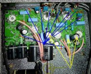
1. Move the 120uF cap (marked with the grey arrow in the picture below) slightly to the right.
2. The point where the -pin of the 120uF cap is soldered to the PCB (thick ground trace) will be the star-ground point.
3. Cut through the ground trace at the points marked with the short red lines.
4. Use an insulated wire to connect the points on the cut pieces of the ground trace directly to the star-ground point (blue lines in the picture show the connections).
5. Pull out the -pins of the yellow marked caps and connect them to the star-ground using separate (insulated) wires.
6. Take a piece of the shield from an old cable and use it to cover the four-wire flat cable running from the speakers terminal. Then connect the shield to the star-ground.
This is the correct wiring of the star-ground. If the hum is the result of a poorly designed PCB, it should be gone after you've done this. Of course, there is a possibility that the hum may be induced by the ripple voltage from the poorly designed power supply. In that case, you'll require additional caps in the power supply.
Caution: If you feel uncomfortable with the above procedure for any reason or you intend to resell the amplifier, I strongly advise you to forget about the whole thing.
Regards,
Milan
It seems that the problem may be a poorly designed PCB (ground traces in particular). To cut the long story short, I'd do the following if I were in your shoes:
1. Move the 120uF cap (marked with the grey arrow in the picture below) slightly to the right.
2. The point where the -pin of the 120uF cap is soldered to the PCB (thick ground trace) will be the star-ground point.
3. Cut through the ground trace at the points marked with the short red lines.
4. Use an insulated wire to connect the points on the cut pieces of the ground trace directly to the star-ground point (blue lines in the picture show the connections).
5. Pull out the -pins of the yellow marked caps and connect them to the star-ground using separate (insulated) wires.
6. Take a piece of the shield from an old cable and use it to cover the four-wire flat cable running from the speakers terminal. Then connect the shield to the star-ground.
This is the correct wiring of the star-ground. If the hum is the result of a poorly designed PCB, it should be gone after you've done this. Of course, there is a possibility that the hum may be induced by the ripple voltage from the poorly designed power supply. In that case, you'll require additional caps in the power supply.
Caution: If you feel uncomfortable with the above procedure for any reason or you intend to resell the amplifier, I strongly advise you to forget about the whole thing.
Regards,
Milan
Attachments
Well it looks like I don't have much to lose! Sure if it doesn't work, I can always resolder the trace. Heres the thing though, The PCB is double sided, with the bigger trace on the underside. Could one be the PS ground and the other the signal ground? Do I cut it both sides at the points marked?
Also whats the easiest way to cut the trace?
Fran
Also whats the easiest way to cut the trace?
Fran
Well, I can't see the other side of the PCB so I can't really say if you should cut the PCB on both sides at the points marked. But, as a thumb rule, each piece of the ground trace you cut should be connected back to the star-ground.
You can use a utility knife (that is a razor blade knife) to cut the ground trace.
Regards,
Milan
You can use a utility knife (that is a razor blade knife) to cut the ground trace.
Regards,
Milan
OK, thanks for the advice and pointers. I have printed out your instructions Milan and will study them during tomorrow.
One last question before bed!!!
The caps C1 and C2 in the most recent schematic - are rated as 100uF 200V. I have measured 140V across C1 but 275 across C2. Should I change these to a bigger voltage reading?
Fran
One last question before bed!!!
The caps C1 and C2 in the most recent schematic - are rated as 100uF 200V. I have measured 140V across C1 but 275 across C2. Should I change these to a bigger voltage reading?
Fran
woodturner-fran said:I have measured 140V across C1 but 275 across C2.
Something's not quite right here. If you measured 140V across C1, you should be getting about the same value across C2 as well. Please, repeat the measurements.
You should measure about 270V (double the value of C1) across both 120uF caps.
Good night,
Milan
Sorry, I should have been more explicit. If you measure across terminals of cap1 then you get 140V, across cap2 the same 140V, but across both of them (neg of one to pos of the other) 280V. So that adds up. I guess that answers my own question, theres only 140V across each so then the 200V rating is AOK.
It seems that the easiest step to take, although maybe not the most correct one, would be to put in bigger caps in the power supply. If the ones that are there right now are 100uF/200V and 120uF/400V what size caps should I think of putting in there.
Its just that with the PCB being double sided, I'm not sure if its a bit beyond me, but then its late and I'm tired! I will also check and see if the trace on the top and bottom of the board are connected and where.
I still have to find out about this B+ voltage of 270V. It seems the tubes max is 250V. Can the tubes withstand this?
Also - those trim pots where the AC heaters are grounded. I opened one of them up so that there was no resistance and I got the hum, it only took a few turns to bring that hum back down.
Till tomorrow!
Fran
Hi all,
I didn't get to do anything with the amp tonight, but a friend of mine also bought one of the same amps and he reckons he has no hum at all! Which leads me to think that it mustn't be a design fault as such, but an implementation of it in my amp.
Now I also know other guys who have this amp and most of them have hum but at varying levels.
More later...
Fran
Oh, yeah.
and I think (!) I've picked up a set of russian 6P1P-EV and 6N1P-EV tubes for a song, so I'll try that too. They're mil-spec tubes so maybe they will perform a bit better.
Thing is, even with the hum there, I went back to my (admittedly not brilliant) SS headphone amp and the difference was not small. Tubes outshone by a long way. Even if I can't get rid of the hum, its still a keeper,
Fran
Another update. I put the bottom plate back onto the amp last night and I notice that the hum was stronger in the right channel. So I tried swapping around tubes, the 6N1 input tubes made no difference, but moving around 1 of the 6P1 driver tubes made the "stronger" hum change sides repeatedly. It was easy to keep track of this tube because it had a stronger bluish glow inside the tube than the others (although they all have this glow - is this normal?)- no, no its not one of those LEDs that seem to be the rage in chinese amps at the moment! This glow is inside the tube.
2 guys I know who bought this amp had faulty tubes from the outset.
Sophia Electric, according to their website, use "specially treated" military spec russian 6P1P tubes "for low noise"
So perhaps this hum is tube related.
I'll only know when I get the russian tubes in a couple of weeks.
Fran
2 guys I know who bought this amp had faulty tubes from the outset.
Sophia Electric, according to their website, use "specially treated" military spec russian 6P1P tubes "for low noise"
So perhaps this hum is tube related.
I'll only know when I get the russian tubes in a couple of weeks.
Fran
Another small update:
I have started reading over some of the posts again and decided to look more closely at the AC heaters.
The 2 preamp tubes (6N1) are connected to ground via "virtual" centre tap - ie a trim pot with the wiper connected to ground. On closer inspection this pot only went to 50R. Nearly all that I've seen in my recent reading usually suggests 100R. So I took out the trim pots and replaced them with some 90R resistors that I had - not exact I know but still almost double what is there. Amp is a little quieter - the hum is smoother. Now I'm starting to think that there was a mixture of 60Hz and 120Hz - the 60Hz maybe from the AC heaters and the 120Hz from ????
Incidentally, the power tubes 6P1 - the heaters here aren't connected to ground at all as far as I can make out, just directly back to the power transformer. Shouldn't these be connected in the same way as the preamp tubes???
Fran
- Status
- This old topic is closed. If you want to reopen this topic, contact a moderator using the "Report Post" button.
- Home
- Amplifiers
- Tubes / Valves
- hum in amp!