I was thinking; and quite possibly incorrectly, that if it were flat and I put the high pass filter on it the bottom would get trimmed back a bit anyway. But then I remembered you were saying something about shooting for a flat response with the port wouldn't necessarily sound good. I eas just not fully comprehending that.
Last edited:
You weresatonf I probably wouldn't like the larger box with the flat response if I liked the sound of a closed box. So I said; OK, then what should I be shooting for if not flat? And, you can feel free to elaborate on that.
If you want a ported box to sound like a sealed box you need to make the ported box have the same frequency response as the sealed box. I showed a picture and talked about this in detail in post 5, and in the post that I linked to in post 5.
I was thinking; and quite possibly incorrectly, that if it were flat and I put the high pass filter on it the bottom would get trimmed back a bit anyway. But then I remembered you were saying something about shioting for a flat respise with the port wouldn't necessarily sound good.
A high pass filter will bring it down a bit, but with a 4th order it will only affect up to a couple hz above the filter frequency and only bring them down a couple db. You will see when you start playing with the high pass filter in Hornresp. With a 2nd order it will affect stuff a bit higher but it's not going to make a max flat alignment look like the rising response of a sealed box.
Anyway, what you are talking about here is using the high pass filter as a form of eq. If this is what you want you could just use eq to bring it down, but since you don't really want a 600 liter box anyway, just make the box smaller and don't worry about the high pass filter. You'll see, a 4th order high pass doesn't affect anything inside the passband too much, just a couple db loss at the filter frequency.
I own two of the HT18 D2's. I have the 2 coils wired in series, then the two speakers wired in parallel. Both are being powered off of one channel on an iNuke3000. The iNuke gives the perfect amount of power for them, anything more and it will start to burn them.
Here's a link to my build with them, If you want the plans for any of those enclosures, I can look for them, I have them somewhere. Although it doesn't sound like a back loaded horn is what your looking for. I hope that thread can be of some help!
Here's a link to my build with them, If you want the plans for any of those enclosures, I can look for them, I have them somewhere. Although it doesn't sound like a back loaded horn is what your looking for. I hope that thread can be of some help!
 Hopefully this weekend!
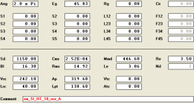
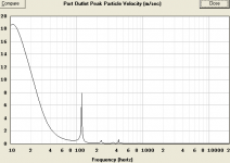
playing around with the small box now for practical reasons (plus counting on getting a little room reinforcement(?). At 20 Hz it is 10 m/s with an 8 inch port... but the length is about 55 inches, which seems quite long. Also that means that the port is burning up about 44 liters of box volume... and will have to do a whoop-tee-doo since the box is only 36 inches tall -- I will put a radius at the port entrance to the box. I guess with a little stuffing the port resonances aren't a big deal?
revised and unmasked
revised and unmasked
Attachments
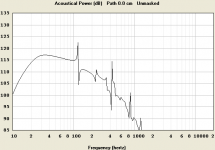
Even without stuffing the natural box losses caused by less than infinitely stiff panels and the low pass filter will take care of most of the very sharp and narrow resonance issues that you see. Wider resonances are only subtly damped but the really narrow ones sometimes completely disappear and anything above the low pass filter frequency will be attenuated.
Also if you wanted to, you could make the port quite a bit shorter and smaller while maintaining the same port velocity by making it a flared port. It's more difficult to sim and to build but there are distinct advantages to be had.
Also if you wanted to, you could make the port quite a bit shorter and smaller while maintaining the same port velocity by making it a flared port. It's more difficult to sim and to build but there are distinct advantages to be had.
So, if all the narrow resonances aren't there anyway, why not use the 'masked' output?
I always radius the ends of the port (and I got some pretty big round-over bits). are you talking about something other than a round-over bit? If it is not round, is there a formula for the shape? Once of my favorite details back in the day was to inset a piece of hardwood at the port an round it over. This gives it a really nice finished look if the box is made from MDF with a nice veneer.
How do you get more than one plot at a time to graph? Can I now model the mid-bass driver and plot it with the sub driver to see how the interact?
So, if all the narrow resonances aren't there anyway, why not use the 'masked' output?
SOMETIMES the really narrow resonances completely disappear, sometimes they are just attenuated. The wider ones won't ever disappear. Just add a very small bit of stuffing to the sim to get a vague idea of how internal box losses will affect the resonances.
I always radius the ends of the port (and I got some pretty big round-over bits). are you talking about something other than a round-over bit? If it is not round, is there a formula for the shape? Once of my favorite details back in the day was to inset a piece of hardwood at the port an round it over. This gives it a really nice finished look if the box is made from MDF with a nice veneer.
I'm talking about a much larger flare than you can do with a roundover bit. Here's a Danley sub with a flared port, there's a couple of pics on the first page of this thread - http://www.diyaudio.com/forums/subwoofers/226235-featherweight-title-fight.html
Personally I would do it a bit different, a more dramatic flare (up to but not exceeding 45 degrees) at both the port entrance and exit and a straight section in between. You can make the port smaller while maintaining the same tuning and velocity by using flared ports like this, either flared slot ports as shown in the Danley sub or with premade (or home made) round plastic flared ports. This page shows how to make your own round PVC flared ports but you are pretty limited when it comes to how large the radius can get - Heat Moulded Port Flares
How do you get more than one plot at a time to graph? Can I now model the mid-bass driver and plot it with the sub driver to see how the interact?
You can use the "compare previous" or "compare captured" feature in Hornresp to show two graphs, but it won't show how the two graphs will interact.
Recently Hornresp was updated to simulate Synergy horns, so you can view how two or three different drivers will interact when firing into the same horn. Haven't tried this feature yet, no idea if it will let you do what you want. Probably not. But maybe. if not there's always Akabak, you can simulate entire systems but there's a steep learning curve. Or you can do separate sims, save the frequency response and impedance graphs as .frd and .zma files and use a program like Bagby's Passive Crossover Designer to see how they will interact. With that program you can sim the passive crossover on the mid driver too, and even add a tweeter and a full passive crossover for the system. The sub active crossover can be done in Hornresp before you make the .frd and .zma files. i certainly wouldn't use a passive crossover on the sub.
- Status
- This old topic is closed. If you want to reopen this topic, contact a moderator using the "Report Post" button.
- Home
- Loudspeakers
- Subwoofers
- HT 18 DVC subwoofer build