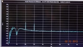
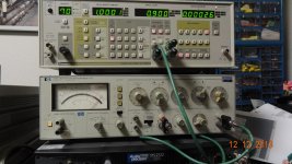
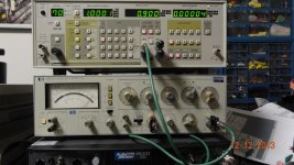
...and add the 2H trim pot with a small size 20-28 turn 5k pot. You can do more but you should have access to test equipment to do it right. at least a sound card type FFT to make adjustments for minimum thd. You can not use the 339A distortion analyzer to get below .001% as the analyzer isn't capable of resolving it.... without a major remake of that portion....go to the output monitor with a ADC/FFT and adjust the oscillator for lowest distortion.
-RM
-RM
Last edited:
The analyzer section of the 339A isn't as easy to improve. Here is what you might get -- to within 3dB of accurate level in THD+N to -100dB. But below -100dB it isn't accurate and you wont know what the true level is without going to the monitor output and looking there - using a modest FFT ADC system, like the QA400, it can be reasonably accurate as the residual levels are low enough (well under 1v). The 339A can handle up to 300vac input (if using the correct scale) and doesn't get blown up by it. So, it makes power amp testing a little safer to do.
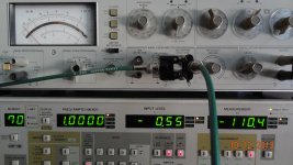
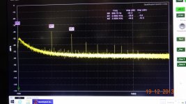
[zero is what ever setting the distortion range switch is set... in this case -80dB = 0 on the FFT]
Thx-RNMarsh


[zero is what ever setting the distortion range switch is set... in this case -80dB = 0 on the FFT]
Thx-RNMarsh
Last edited:
Hi all
I am a older greenhorn if that makes any sense, and this is my first post. I recently bought two hp339a's with serial #'s starting with 2520a, they both have the extended range kits installed from the factory. One was calibrated in 08, the other in 03. They came from the coast gaurd.
Question 1: After reading Artek's manual, they purpose a lot of changes, are all these mods required plus the suggested mods on this thread?
Question2: In a lot of measurements they use a 600 ohm resister I believe in series. How do I know when to use this resistor and when to not.
Question3: I was thinking since the meter takeoff is isolated, can i use the meter for spl if i plug a mic to the input.
confession: I haven't even put power to these units yet as I am just learning their functions. Also a 331a came with them. Any help would be appreciated. Links to other forums etc.
thanks
Angelow
thanks Richard...I was hoping I could. Would i need a pre-amp for the mic or would the input amp of the hp339a do the job? I have some electronic theory but ain't too practical...hope that will change. From what I read these were/are nice instruments.
Thanks again
Mike
If you have a 339 with the extended range it goes down to 100uV full scale. That's more than enough gain for a mic. Keep in mind the input impedance is 100k and may not match your mic. If your using a condenser type it shouldn't be a problem. There is a capacitance to the 100k impedance and the input has a wide band choke. This may effect the flatness.
Would it be possible to make a "Cliff Notes" list of mods to do to the 339? I would love to hotrod mine a bit.
For the oscillator or the analyzer?
The oscillator is the simplest. Replace the oscillator op amp with a LT1468. Remove all the compensation components around the oscillator's op amp.
Replace the resistor coupling the AGC output to the Jfet with a good quality trim pot. A 3k 10-22 turn trim should do.
Richard might have some advise on which caps to replace if any.
I rebuilt the power supply in mine. Replace all the caps. You might try playing around with the AC coupling caps between the ground and AC main input. I cleared up a bit of ground noise doing this.
Yes, replace any tantalum coupling caps with high quality bipolar types and replace the output level pot.
carefully clean all the switch contacts.
-RNM
Yes, replace any tantalum coupling caps with high quality bipolar types and replace the output level pot.
carefully clean all the switch contacts.
-RNM
How hard is it to replace the output level pot, 10-30 min. job or hours?
How hard is it to replace the output level pot, 10-30 min. job or hours?
The output level pot is easy to change. Loosen the screws on the shaft extender and spin the nuts off.
20 min tops.
Other notes,
The bottom of the board is completely exposed once the analyzer is oped up. It's a bit tight from the top of the board but all your doing is inserting components. Just remember to remove all the compensation and clamping components around the op amp for the oscillator. If you use an LT1468 the comp is wrong and not needed. There's is not much to go wrong. Just be careful when making adjustments that you don't short the case of the Jfet. It's very close to one of the pots and if it shorts it's toast.
Last edited:
The output level pot is easy to change. Loosen the screws on the shaft extender and spin the nuts off.
20 min tops.
Other notes,
The bottom of the board is completely exposed once the analyzer is oped up. It's a bit tight from the top of the board but all your doing is inserting components. Just remember to remove all the compensation and clamping components around the op amp for the oscillator. If you use an LT1468 the comp is wrong and not needed. There's is not much to go wrong. Just be careful when making adjustments that you don't short the case of the Jfet. It's very close to one of the pots and if it shorts it's toast.
Ok, now I am running out of excuses - time to open the case and get to it.
Gents,
Some good info here. I'm interested, but don't have an HP339A yet.
I'm intrigued about using the ocs portion, then again, I could use
a distortion meter also, for audio and music tube amps and the like.
I looked through the manuals posted, what a pain. I hate online
stuff, esp schematics. I love print. However, for browsing around
we are lucky so much stuff is available on line. ; )
I was reading up on RNMarsh's recommendations for using hi quality
bipolar caps, (ridding the p/s of tants) what do you recommend?
What is a good price point?
Then there was davada's recommends too.
Holy Smokes, then I tried reading the low distortion thread too...
That is a lot of work you and others are doing. Wish I had a
set up like that.
So I'm peicing together and upgrading my bench from variacs,
big resistors, Fluke DVMs, and other simple stuff to more sophisticated gear.
It's gotten to the point where I don't even like working on the consumer
trash any more.
So I'm thinking of doing the HP 339a. Or are there better things to
spend my time and money on?
--Sync
Some good info here. I'm interested, but don't have an HP339A yet.
I'm intrigued about using the ocs portion, then again, I could use
a distortion meter also, for audio and music tube amps and the like.
I looked through the manuals posted, what a pain. I hate online
stuff, esp schematics. I love print. However, for browsing around
we are lucky so much stuff is available on line. ; )
I was reading up on RNMarsh's recommendations for using hi quality
bipolar caps, (ridding the p/s of tants) what do you recommend?
What is a good price point?
Then there was davada's recommends too.
Holy Smokes, then I tried reading the low distortion thread too...
That is a lot of work you and others are doing.
set up like that.
So I'm peicing together and upgrading my bench from variacs,
big resistors, Fluke DVMs, and other simple stuff to more sophisticated gear.
It's gotten to the point where I don't even like working on the consumer
trash any more.
So I'm thinking of doing the HP 339a. Or are there better things to
spend my time and money on?
--Sync
Well, a stock 339A gives you a wide band ac voltmeter, an oscillator and analyzer. A stock one will do you pretty well as long as you have no interest in reading below .001%. The basic mods will do you just fine. The best bang for the dollar invested. But they are old and finding one in very good condition takes time.
WE just went crazy on the 339 to see how far we could take it. I wanted to go very very low for thd on a budget. It turned out for me to not be such a low budget as the ultimate limitations got in my way and I ended up buying SOTA commercial gear.
An alternative is an ADC with FFT software and your PC. It will also cost about the same and is also accurate to .001% or -100dB. It isnt as flexible without adding input voltage ranging add-on and if you want to see below -100dB you can also add a notch filter.
And, then you can have both and use the residual output from the 339A built-in notch filter into an ADC/FFT.
Thx-RNMarsh
Last edited:
Richard might have some advise on which caps to replace if any.
.
The coupling caps should be changed to lower distortion bipolar type. Use only well known high quality brands and caps rated for 105C as they are more linear and have a longer stable performance life.
-RNM
The coupling caps should be changed to lower distortion bipolar type. Use only well known high quality brands and caps rated for 105C as they are more linear and have a longer stable performance life.
-RNM
That would be the electrolytic types as opposed to film/foil or
sealed paper in oil types.
I find it odd that tube heads like using film coupling caps yet
the solid state folks use the electrolytics.
Why is that?
- Home
- Design & Build
- Equipment & Tools
- HP339A distortion analyser
