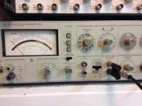
I recently acquired an HP-339A distortion analyzer. I had to do some repairs on both the oscillator section and the notch filter (auto-null) circuits, but now everything seems to be working perfectly. Now I need to do the calibration (as best I can). This is a hobby application, not a business, so I am not inclined to send it out and pay for calibration.
Looking at the service manual for the 339A, the alignment procedures seem to be unnecessarily complicated, requiring way more equipment (that I don’t have) than what is really needed. Like the setting of the phase and amplitude nulling pots. The manual has you use a spectrum analyzer to look at the fundamental (at 1kHz) of the residual output and null it at least 100dB down. Makes sense, but it seems you get the same result easier by just adjusting the pots for the lowest residual on the distortion meter. I looked at it both ways and the answer is the same. Nulling the meter reading is just way easier. The high frequency adjust is an even better example. The manual requires a spectrum analyzer with a tracking generator.
First a low distortion oscillator (why not use the one in the 339?) is set to 10kHz and applied to the distortion input. Then a 1kHz sine wave is mixed in with it and the level adjusted to -80dBV. This is then the reference level on the spectrum analyzer. Then the 1kHz signal is changed to 20kHz and the high freq adjust (variable capacitor) is set so the 20kHz signal is 0.3dB below the 1kHz level.
Again, the whole thing seems like it can be done without the spectrum analyzer / tracking generator by just using the distortion reading on the meter. Set the 1kHz level to -80dBV and then adjust so the 20kHz level reads 0.3 dB lower. The only one I am not sure about is the Input Balance Adjust (A4R65). It looks like the procedure has you look at the residual output at the second harmonic of a 10Hz signal and null the second harmonic. Seeing a 20Hz signal 100dB down with my old spectrum analyzer isn’t an option, so I just again, nulled the pot for the lowest reading on the distortion meter and that seems to have worked fine. So, long winded story over, and to my question…
How do you guys calibrate the HP-339A? Do you follow the service manual, or do you have ‘work arounds’ that are pretty much good enough? The calibration for the Sound Technology ST1700A doesn’t require any spectrum analyzer or tracking generator….
Terry
I haven't worked with the 339A, but with the HP8903A/B and HP3562A, I just followed the service manual. Those instruments are younger than the 339A and used as much of the instrument itself to perform the calibration as possible. But depending on how the 339 works that may or may not be possible.
I doubt the alignment procedure for the 339A would require a spec an with 100+ dB dynamic range. The spec an's I've seen from that era all have 80 dB dynamic range.
That said, an external computer sound card has higher than 100 dB dynamic range... Spectrum analyzer software is pretty common.
~Tom
I doubt the alignment procedure for the 339A would require a spec an with 100+ dB dynamic range. The spec an's I've seen from that era all have 80 dB dynamic range.
That said, an external computer sound card has higher than 100 dB dynamic range... Spectrum analyzer software is pretty common.
~Tom
Your approach is fine -- you use the meters on the 339A front panel, you just adjust for the lowest distortion reading or null. It isn't an absolute way to do it, but it ends up giving the best performance. The absolute level cal needs the equipment HP lists.
What was your instruments problem and what part(s) solved it? Can be useful info for others if they have same problem.
Thx-RNMarsh
What was your instruments problem and what part(s) solved it? Can be useful info for others if they have same problem.
Thx-RNMarsh
Last edited:
I bought it from eBay as a 'parts or repair'. It was in fairly good shape, with all of the front panel knobs in place. But someone with less than stellar skills had been in it. The oscillator had a signal, but not great distortion. The distortion didn't null well on a low distortion input signal, and even the voltmeter didn't read right. The switches were not properly aligned with the front panel knobs, so the switches were not getting set to the right positions. Fixing that fixed the voltmeter. The oscillator had a bad op-amp (U2B) so that the fast loop worked, but the slow one didn't. Somewhere along the line the FET that adjusts the gain for the loop died too. I don't know if it was on the way out and just died or if I somehow killed it in my troubleshooting. Anyway, replacing the FET (VCR2N) and op-amp (LM348N) got the oscillator working great.
The distortion section was funny. Apparently someone tried to remove the A4 board without removing the one screw that secures it. Both of the plastic card ejectors were snapped off, as well as one of the leads on a pot (R65) that would be in a location to grab the board and pull hard. Easy fix there. But it still wouldn't null. Carefull examination of the switch deck that selects the resistors in the notch filter showed some of the metal switch wafers were bent badly. I had to remove the switch (all four decks) from the pcb, carefully disassemble them and remove the metal contact from the switch wafer and straighten the contact. Got it all back together and then the distortion would null on the X1 and X10 ranges, but not the X1k and X10k ranges. Looking at the schematic, only one part could affect the X1K and X10K and not the others - C14 on the A3. So I poked it with a plastic tool and it started working. I reflowed the solder for C14 and the switch that selects it, and everything seemed fine, but I went ahead and replaced C14 anyway (1800pF 1% mica).
Now (after alignment) everying seems to be working great. 1kHz residual is 0.0014%.
Terry
One last bit of work to the HP-339A. A couple of the front panel switches had the text messed up. One looked good except one number had 'fallen off'. Instead of 10k, it said 1 k. I don't know how the 0 fell off. The remainder of the text on the switch looked great. This one I fixed with a bit of black Krylon Fusion (for plastic) paint. It was in a spray can, but I shot a bit into the cap and very carefully applied it with a toothpick. It looked a little ragged, but after it dried a bit, I went back with an exacto knife and carefully cleaned up the edges. Not perfect, but very acceptable.
The other switch was way worse. Someone had glued the clear disc with the letting onto a replacement knob. In the process, they managed to destroy a good bit of the lettering, and worse yet get epoxy all over the back side of the clear plastic disk. It looked like crap. So I sanded off all of the old lettering and epoxy from the back side of the disk. I used progressively finer grades of wet sand paper (120, 220, 400, 600, 800, 1000). Then I finished off with a plastic scratch remover and polish for automotive applications. I ended up with a perfectly clear disc. To get the lettering back on, I used ink-jet printable decal paper. I was able to get a pretty decent image with Microsoft Word. It took a bit of playing around but I finally got the text in the right position and size around the circle. You print this (image reversed) onto the decal sheet, spray it with a clear protective layer, then apply it like the decals you used on your plastic models (soak in water to release the backing). The result is pretty good.
I see that there is even a dry rub on decal version of these sheets that might even be better.
Terry
It is hard to find one with all of the switches in good shape. I was pleased to find one that had all but one switch in pretty good condition.
BTW, if anyone needs to remove the front panel of the 339, it is actually pretty easy to do. At least freeing it enough to work on things behind it (like changing the binding posts that are often broken). Only four screws hold the front panel onto the chassis. I disconnected the couplings that connect the shafts to the switches in the rear of the unit. If you disconnect the coupling between the front shaft and the rear shaft, it is pretty easy to get to, and it lets you pull the front panel away from the chassis a couple of inches. You need to remove the knobs from a few of the front panel controls, not all of them. Just the ones that have the controls mounted on the main chassis.
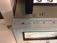
When you put it back together, the flats on the shafts should align. That probably is obvious to everyone, but it was evidently not obvious to whoever worked on the unit I purchased. Here is a picture of the switch with the lettering I had to replace.
Terry
BTW, if anyone needs to remove the front panel of the 339, it is actually pretty easy to do. At least freeing it enough to work on things behind it (like changing the binding posts that are often broken). Only four screws hold the front panel onto the chassis. I disconnected the couplings that connect the shafts to the switches in the rear of the unit. If you disconnect the coupling between the front shaft and the rear shaft, it is pretty easy to get to, and it lets you pull the front panel away from the chassis a couple of inches. You need to remove the knobs from a few of the front panel controls, not all of them. Just the ones that have the controls mounted on the main chassis.
When you put it back together, the flats on the shafts should align. That probably is obvious to everyone, but it was evidently not obvious to whoever worked on the unit I purchased. Here is a picture of the switch with the lettering I had to replace.
Terry
Attachments
It is the screws in the four corners of the frame. Removing them lets the front panel come out of the frame. You will have to remove the knobs from the bottom row of controls since those are mounted on the frame or boards. But the top row is different. Removing those knobs doesn't buy you anything since the switch detent mechanism is mounted to the front panel. But as you pull the front panel away, the shafts that extend to the actual switches on the boards will slide out. I found that disconnecting the coupling that connects the front shaft to the rear shaft for each switch let me get the front away from the chassis just far enough to get in there and work on things. But if you need to pull it away even further, you will have to disconnect the shafts from the detent mechanism on the front panel. If you do that, I suggest you use a paint dot or similar to mark the orientation of the shaft in the detent mechanism. There are two set screws on the detent mechanism collar, but only one flat on the shaft. So there is a 50-50 chance of getting the shaft oriented wrong when you put it back together. No big deal, just a bit more fiddling around to figure out the correct position.
Another way would be to remove the knobs from the top row of controls and then remove the nut that holds the detent mechanism to the front panel. That might even be easier, but I had already disconnected the shafts since they were misaligned when I got the instrument. When you put it back together, there is a pin on the detent mechanism that fits into a hole on the front panel to orient the switch and keep it from rotating.
I didn't have to disconnect any wires or anything since I was able to pull the front panel away from the chassis far enough to do what I needed, but it looks like most things are connectorized. But you better mark them well if you disconnect them, the manual does not show the chassis assembly very well, so you will end up chasing the schematic to figure out where to reconnect everything.
And remember, if you want to remove the plug in card (A4 board - nulling circuitry), there is one small screw in the center of the card that holds it in place. If you don't remove the screw, you will snap off the card ejectors and the card still won't come out. Just ask whoever worked on the anaylzer I bought before I got it.")
Terry
Another way would be to remove the knobs from the top row of controls and then remove the nut that holds the detent mechanism to the front panel. That might even be easier, but I had already disconnected the shafts since they were misaligned when I got the instrument. When you put it back together, there is a pin on the detent mechanism that fits into a hole on the front panel to orient the switch and keep it from rotating.
I didn't have to disconnect any wires or anything since I was able to pull the front panel away from the chassis far enough to do what I needed, but it looks like most things are connectorized. But you better mark them well if you disconnect them, the manual does not show the chassis assembly very well, so you will end up chasing the schematic to figure out where to reconnect everything.
And remember, if you want to remove the plug in card (A4 board - nulling circuitry), there is one small screw in the center of the card that holds it in place. If you don't remove the screw, you will snap off the card ejectors and the card still won't come out. Just ask whoever worked on the anaylzer I bought before I got it.
Terry
Attachments
A good source for the manual- which gives the calibration procedure and schematics etc is from ->
www.ArtekManuals.com
"The worlds largest supplier of PDF manuals for out-of-print test equipment manuals"
Thx-RNMarsh
www.ArtekManuals.com
"The worlds largest supplier of PDF manuals for out-of-print test equipment manuals"
Thx-RNMarsh
Yep. I ordered the 339A manual from them on their ebay store, although after I received it I found they suggest going straight to their web page instead. It is a very good clear scan that is readable, unlike some of the free ones you find on the web. And the large foldout pages are scanned as a single page. Much nicer than in pieces. The only thing I don't like is that they are 'protected' PDFs, so you can't print them. I'm old school and prefer to work from a printed schematic when troubleshooting. Paging through a document on a computer screen is tedious. So I ended up printing out the schematic pages that are free on the web and taping them together to make the pages complete. I referred to the Artek manual when the free one wasn't legible.
Terry
Terry
The manual shows pics of cabeling and one has a 600 resistor in it. I would like a set of these if anyone knows where to get them.
I also think my 339a oscillator is bad since looking at it on an oscilliscope it is extremely fuzzy like the triangular wave has a lot of noise. Does anyone have a pic of what the wave looks like they could post?
I also think my 339a oscillator is bad since looking at it on an oscilliscope it is extremely fuzzy like the triangular wave has a lot of noise. Does anyone have a pic of what the wave looks like they could post?
- Status
- This old topic is closed. If you want to reopen this topic, contact a moderator using the "Report Post" button.
- Home
- Design & Build
- Equipment & Tools
- HP-339A Calibration