Please my friends,tell me how to protect my speakers of badly sound after power on amplifier, and when you shut down the amplifier
Welcome to the protection of the DC voltage,but most important to me that the specific phenomenon of poor sound on the speakers, when you turn the amplifier, and after exclusion of the same.
Please seed may be too complicated for the project DIY.
Thanks!
Welcome to the protection of the DC voltage,but most important to me that the specific phenomenon of poor sound on the speakers, when you turn the amplifier, and after exclusion of the same.
Please seed may be too complicated for the project DIY.
Thanks!
Pigy,
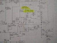
I bought a few weeks back on ebay, TA7317P chips from Toshiba.
I tried them on a breadboard, the circuit works fine.
It has both the delay on and direct off function as you require.
With component values of the circuit below it also shuts down below frequencies of 5Hz.
The nice thing with this chip is, that is work up to voltage of 60Vdc. Untill now I had for each amp I've made, different DC detection, delay on an direct off circuit.
I use this circuit to drive two AMPLIMO LRZ relay's, on for each channel.
Attachments
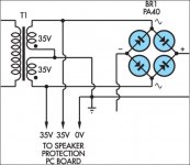
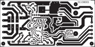
From SiliconChip magazine
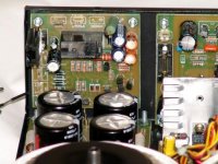
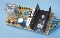
Well, this is not an universal solution, but works very fine.
It has been designed based upon a circuit from Silicon Chip magazine, found also on the internet.
If you find any trouble ask me and I can help you getting it up and running.
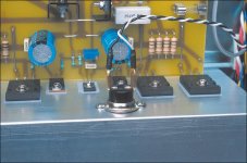
My home DIY amp uses a pair of boards (one for each channel) with 100% satisfaction.
Further information and board layout may be found here: * "http : // dx . kinghost . net"(Loudspeaker Protection section: http://www.nabucoeletronica.com.br/dx/files/spkprot-schematic.pdf).
It would be nice if you could post your amps' schematics, so it would be easier for us to help attaching this unit.
Regards,
Max.
Well, this is not an universal solution, but works very fine.
It has been designed based upon a circuit from Silicon Chip magazine, found also on the internet.
If you find any trouble ask me and I can help you getting it up and running.
My home DIY amp uses a pair of boards (one for each channel) with 100% satisfaction.
Further information and board layout may be found here: * "http : // dx . kinghost . net"(Loudspeaker Protection section: http://www.nabucoeletronica.com.br/dx/files/spkprot-schematic.pdf).
It would be nice if you could post your amps' schematics, so it would be easier for us to help attaching this unit.
Regards,
Max.
Attachments
Last edited:
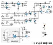
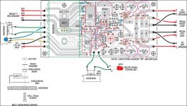
More one Silicon Chip article
You may find more information here:
http://www.siliconchip.com.au/cms/gallery/article.html?a=103286&i=6
Regards,
Max.
You may find more information here:
http://www.siliconchip.com.au/cms/gallery/article.html?a=103286&i=6
Regards,
Max.
Attachments
There is also a third-part kit available, related to the circuit described here: http://www.siliconchip.com.au/cms/A_109008/article.html
The kit is here: Universal Speaker Protection and Muting Module Kit - Jaycar Electronics
The kit is here: Universal Speaker Protection and Muting Module Kit - Jaycar Electronics
Last edited:
- Status
- This old topic is closed. If you want to reopen this topic, contact a moderator using the "Report Post" button.
- Home
- Amplifiers
- Solid State
- How to protect my speakers of ,,tup,, sound?