Hello there,
The place have moved. Took me awhile to find it again.
Just got them now. But they are only 2W 5% for 4 each of 0.47
and 0.33 and 0.22
I did not want the white rectangle ones. They have 5W but not the exactly the same values as you have specified. I also have the 10k log dual gang now. How do one wire this pot up? It has 6 contacts. From CD audio out to pot and from pot to the RCA input of power amp. One channel at a time as my power amps are mono blocks.
Birds eye view of the 10k log pot
* * *
* * *
--||--
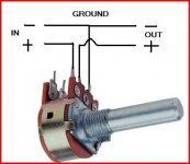
The wiper is always the middle leg. Ground one side as shown and apply the input between the other leg and ground. The signal is always taken from the wiper and ground. If you got the two end connections reversed the pot would work back to front !
This shows just one channel-- just copy it for the other one.
This shows just one channel-- just copy it for the other one.
The sharing of the current is fixed after I replaced the 2N3055 with the Mj21194G that came through the post from On-semi.
They are not perfect but they measusred at 80mV and 71mV for Q2a/Q2 and 83mV and 69mV for Q1a/Q1
So the PSU ripple seems fine. Next thing to try now is to wire up the pot and connect the CD player to the amp and play with the scope to see how well the JLH reproduce the sine wave and square wave. Is that the right approach? I have warmed up the amp for an hour or so after putting in the new output transistors and the DC offset and Iq is very stable. With the above voltages across the emitter resistors what Iq current I have set the amp at ?
80 + 71 = 151mV ; that would be 1.5A Iq is this right?
Regards,
Hello Chris,
Thats good, sounds like they are much better matched gain wise.
Yes 80 mv across 0.1 ohm is 0.8 amp, and 71 mv is 0.71 amp. Just add them together as you have = 1.51 amps.
I am not sure what the original recommendation was now for the 1969 version. And yours is the "high power version" with multiple outputs. It was all of that though ! 1.6 Amps I seem to remember.
A lot depends on your PSU and the thermal management you have.
Wire the pot up next, just make sure you get the earth at the correct end as shown in the previous picture.
Regards Karl
Well some scary moments
After I wired up the pot and played with the scope and amp for a little while, everything seems fine and then I unclipped the clip from the RCA input of the amp and I made some sparks after that the scope was showing the amp was acting strange with some strange looking sine waves comes and goes with no input from the CD player(disconnected); also the Iq current went up from 70mV to 200mV so I shut off the amp immediately wait for 5 minutes restart everything and it seems normal again.
Now evrything cool down a bit ,,, so am I
Took couple of pictures
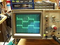
Scope settings for both channels
Sec/Div set at 0.2ms
Volts/Div set at 0.5V
Top trace is from CD player thru the volume pot to the JLH and using 1X probe connect at the speaker outputs.
Bottom trace is direct from the CD player to the scope using RCA interconnect for compare purpose.
The CD is playing a 1Khz square wave.
Something is not right here. My camera seems to over expose but I can not use flash to take the pics.
Hope you can make it out of what the traces are telling
After I wired up the pot and played with the scope and amp for a little while, everything seems fine and then I unclipped the clip from the RCA input of the amp and I made some sparks after that the scope was showing the amp was acting strange with some strange looking sine waves comes and goes with no input from the CD player(disconnected); also the Iq current went up from 70mV to 200mV so I shut off the amp immediately wait for 5 minutes restart everything and it seems normal again.
Now evrything cool down a bit ,,, so am I
Took couple of pictures
Scope settings for both channels
Sec/Div set at 0.2ms
Volts/Div set at 0.5V
Top trace is from CD player thru the volume pot to the JLH and using 1X probe connect at the speaker outputs.
Bottom trace is direct from the CD player to the scope using RCA interconnect for compare purpose.
The CD is playing a 1Khz square wave.
Something is not right here. My camera seems to over expose but I can not use flash to take the pics.
Hope you can make it out of what the traces are telling
Attachments
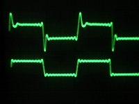
Here is the second pic with the lights turn off in the room. But it is still over exposed.
P.S.
Karl, thank you for your input.. Without your encouragement I would not have gone this far. Although I have no idea what the scope is telling me at the moment some how I feel that I have accomplished something and it is a very good feeling. Thanks again. Owe you a pint!
P.S.
Karl, thank you for your input.. Without your encouragement I would not have gone this far. Although I have no idea what the scope is telling me at the moment some how I feel that I have accomplished something and it is a very good feeling. Thanks again. Owe you a pint!
Attachments
Hello Chris,
"Sparks in the dark" scary stuff !
First question, did you have speakers connected while you are taking the reading.
This is where it gets really difficult without it all in front of you.
Try the measurement again, NO load attached , with just one channel of 'scope connected direct to the speaker output. We know the output from the CD is OK so lets keep it simple.
See if the "overshoot" on the waveform varies at different gain settings of the volume pot. Try from a few 100 mv output up to just below where the amp begins to clip which will be a value just a bit below the supply rail voltage. Make sure you connect your probe ground to the actual speaker negative point, not some point in the PSU.
There was no load attached. The only thing connected to the speaker binding posts were the DC offset checking multimeter and the probe of the scope connected correctly.
The wave form as in the pics looked the same with different volume setting. But when I made a mistake of passing the amp with very high volume the trace moved right of the screen and the amp started to make faint mechanical hum/buzz noise and I dared not to overload it for more than 2 seconds.
The wave form as in the pics looked the same with different volume setting. But when I made a mistake of passing the amp with very high volume the trace moved right of the screen and the amp started to make faint mechanical hum/buzz noise and I dared not to overload it for more than 2 seconds.
Hello Chris,
What you are seeing is called overshoot, the reason why -- well thats another thing altogether. Have you used your own wiring layout for constructing it all ? I can't remember now without re reading it all. Is it on PCB's ?
In all honesty this is where it gets a bit difficult now. There are so many posible reasons why. It could be the way the returns to the zero volt line are made. Every piece of wire has to be treated as a potential "resistance" that could cause an unwanted voltage (signal) to appear across it. The returns for the C4/C2 & R2 are the most important in the amp. They should all go to the star earth not to just any "convenient" earth. I am not saying you have done this -- it's just something to bear in mind.
C2 the 330 pf -- thats fitted is it.
I don't really know what else to advise Chris, at the end of a keyboard there are so many posible pitfalls.
If you are really keen you could try rewiring one channel at a time to a star grounding scheme.
So I should have a better setup for the pot and wiring instead of loose wires soldered to the pot and to 4 aligator clips. And they are not shielded. Now the trace look exactly the same as the CD player connected direct to the scope except the vertical divisions is more with the amp output control by the pot.
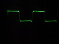
This is the amp trace at 1kHz
PS. now I twisted the wires together and the overshot can be reduced now. It seems the amp is reproducing the squarewave without adding further extra freebies.
This is the amp trace at 1kHz
PS. now I twisted the wires together and the overshot can be reduced now. It seems the amp is reproducing the squarewave without adding further extra freebies.
Attachments
That looks great !!. It's all in the detail isn't it. Earlier on you asked about the quiescent current and I mentioned 1.6 Amp for the original. The updated JLH (not yours exactly -- the one I sent you) mentions I think 2 amps.
What you may find interesting to do is to connect your 'scope across the speaker when it's all playing and see just what voltage you actually put out when it's turned up loud. Try and calculate then what the peak and RMS power is into 8 ohm. You may be suprised how little power you need for normal listening. For ex 6 volts peak (not peak to peak) would be 4.5 watt's peak into 8 ohms. If it were a sine wave swinging 6 volts above and below ground that would then be 12 volts peak to peak or 12/2 which is 6 divided by root 2 ( 12/2=6. 6/1.414=4.24 watts RMS)
So whats next ???
Next Step?
I will check and re-bias the other 3 JLH amps before I build more.
I am using regulated PSU Mj15003 for mid, CLC PSU Mj21194 for high and Chipamp for subs doing active 3 ways per channel.
These JLH amps are so picky about the matching of output transistors may be I should build a matching tool with regulated power supply? Any suggestions?
Mooly said:What you may find interesting to do is to connect your 'scope across the speaker when it's all playing and see just what voltage you actually put out when it's turned up loud. Try and calculate then what the peak and RMS power is into 8 ohm. You may be suprised how little power you need for normal listening. For ex 6 volts peak (not peak to peak) would be 4.5 watt's peak into 8 ohms. If it were a sine wave swinging 6 volts above and below ground that would then be 12 volts peak to peak or 12/2 which is 6 divided by root 2 ( 12/2=6. 6/1.414=4.24 watts RMS)
So whats next ???
Do I set the scope at DC or AC ?
I guess it would have to be AC.
Learning How ...
Chris,
You might want to read these freebies from TEK:
http://www.tek.com/Measurement/App_Notes/ABCsProbes/60W_6053_9.pdf
http://www.tek.com/Measurement/App_Notes/XYZs/03W_8605_2.pdf
They outline how to make measurements with your scope ...
You could also find the User's Manual for your scope at the TEK site ...
- Status
- This old topic is closed. If you want to reopen this topic, contact a moderator using the "Report Post" button.
- Home
- General Interest
- Everything Else
- How to measure JLH Class A with a Scope