Yo Jimmy,
Before you do anything, I would highly recommend that you invest just a few more bucks into Vance Dickason's LOUD SPEAKER DESIGN COOKBOOK. Vance devotes a whole chapter to C/O design and explains the specifics of HOW TO wind coils. Trust me when I tell you that there are some very unforgiving rules you will have to follow if you hope to achieve anything close to predicted results.
Good luck
Chuck
At the adress below you will find very usefull formula to wind air core inductance, and most of the time it is the best way to go
http://home.earthlink.net/~jimlux/hv/wheeler.htm
http://home.earthlink.net/~jimlux/hv/wheeler.htm
Thanks Chuck, I got that book . . .
I got the fifth edition. It has one page about winding inductors, I think. The only thing I pick up on that was significant was that my driver has a resistance of about 7 ohms at 400 Hz where the 12 mH inductors will go. If I make it air-core the resistance will be about .5 ohms, well above what the .35 ohms the author says will "adversely effect" the Q of the driver.
He also states that "metal-core inductors (tend) to saturate and cause distortion at higher operating levels."
Which still leaves me to deside whether I should use air-core or iron core. Although I have a feeling the person who designed my x-over with iron-cores listens to music at moderate levels, so he went with iron-cores, for prehaps the reason above. But I tend to listen to music at high levels, so I might want to go with air-core inductors.
air core vs iron core
Hi Jimmy154,
If I were you I would prefer the air core coil . The iron core is an 'easy way out' to get a low coil resistance while compromising sound. I think the external impedance in a speaker circuit should be les than 10% of the speaker's dc resistance. At this value it just starts affecting the performance. But it probably is not too audible at this level but shows up on paper performance figures.
If you can keep the amplifier output impedance down and cable resistance also low, the coil could probably get away with a large resistance. In my opinion you should also look at the mechanical damping of the speaker. If this is high , then some loss of electrical damping will not contribute so much. I have seen this with some old woofers with very high mechanical damping ( just push the cone to see what I mean). They produced some of the tightest deep bass I have heard . The electronics was just average.
Also remember that many highly regarded amplifiers ( tubed) have pretty high output impedance ( up to 1 ohm or so ). They still sound great . The other thing is that you will really not know the characteristic of the iron cored coil - the way it goes nonlinear with the drive signal unless you spend a lot of time testing that . In my opinion , not worth it. Just have patience and wind the air core coil. I doubt if the loss of some damping will be noticeable , especially at high volume.
I just want to point out here that tight bass sounds much tighter when we play it at higher volume. So you don't have too much to loose. On the other hand with the iron core it will tend to compress the sound as you go louder and introduce distortion. That is far more objectionable than less damping.
Cheers.
Ashok.
Ind. measurment
Jimmy,
I completely agree with ASHOK however there are a couple of tricks I've used in the past which you might consider, if not for your present system, then for the future.
I refer you to page 30 thru 33 of the cookbook on multiple drivers in compound configuration. Tremendous advantages for really HI POWERED systems.
Wiring 2 drivers in parallel halves total impedance and therefore halves coils inductance for a given C/O frequency. Bifilar wind the coils which will use the same amount of copper as with the single driver approch but will halve the coils total resistance.
Just a thought,
Chuck
Some one please tell me if this is right . . .
This has to do with my original post.
The current in the resistor is simply I = V/R
Also I= V/(2*3.1415*L*frequency) = (V/2*pi*F*L)
I know the resistance of each inductor (.0794 ohm/lb). And I know the resistance of the coil is not calculated in these equations. So I think the resistance of the coil would go into the current calculation of the resistor like this, I=V/(Rr+Ri).
Is I=V/(Rr+Ri) correct? Rr is resistance of resistor and Ri is resistance of the coil.
Chuck,
I have considered compound woofers, but my system is 2.5 way. With 3 woofers the nominal impedance at low frequencies would be 2.67 ohms, to low for my amp I think (H/K AVR20II). I guess I will make the inductors air core after all.
3 woofers???
Jimmy,
How do you plan to wire 3 matching woofers such that the current is evenly divided among all 3??? In series=24ohms
Have you considered compound mounting 2 spkrs wired in parallel = 4 ohms and then using the 3rd as a passive radiator effectively lowering box resonance. A 50 ohm wire wound rheostat across the spkr terminals of the PR will allow you to make gradual cone stiffness adjustments which greatly helps to dial the enclosure into the ideal.
Regards
Chuck
Chuck you lost me . . .
I have 4 extra woofers but I'm not sure we understand each other. These are my speakers www.zetagcorp.com/hig4.htm (more or less). The 2 bottom woofers are in the same enclosure. The top one plays from about 4 KHz on down; the bottom from 400 Hz on down. So of course below 400 Hz the woofers are already wired in parellel. Also I don't know if it makes any difference but they're tuned to 38 Hz and that port is stuffed with a T-shirt.
By the way, winding those inductors is a lot harder than I thought it was going to be. Esspecially keeping the wires straight when winding. Now I know why even diy speaker builders have machines for winding inductors. Might look into getting that ferrite again for the four time. I'm really indecisive everyone tells me.
Hi again,
I'm still trying to make my 12 mH inductors, so I guess time is of no value Chuck") I was looking to make an inductor like this one http://home.hetnet.nl/~geenius/Sales_bestanden/image002.jpg It's made out of CRGO (silicon) steel or colded rolled grain oriented steel or in other words electrical steel laminations (I'm pretty sure). It's inductor/transformer with an EI-96 core stacked to 102 mm. It's 15 mH.
I was looking to make an inductor like this one http://home.hetnet.nl/~geenius/Sales_bestanden/image002.jpg It's made out of CRGO (silicon) steel or colded rolled grain oriented steel or in other words electrical steel laminations (I'm pretty sure). It's inductor/transformer with an EI-96 core stacked to 102 mm. It's 15 mH.
I was going to obtain some of these CRGO (type M6) steel laminations and try to glue them together myself with varnish. I say "try" because manafactures do it with a vacum (do it with a vacum ).
).
But then, I was taking apart a washing machine and found out that the motor has electrical steel laminations, but they're not grain oriented I think. They're 5x5" with a 4x4" hole and about 1.5 thick. So I cut them in half and flipped them, so that they make an "I" now, get it? And then wound wire around the "I." They seem have a permability no more than air.
Why is this? Is it because I cut them? Is this what gives the EI cored transformer above inductance? That fact that the core has electrical continuity all the way through and surrounding the core? Is this the right forum for this question? How do I post pictures in this place? Do I have to post them on the internet and then provide links? Maybe that would help me.
I'm still trying to make my 12 mH inductors, so I guess time is of no value Chuck
I was looking to make an inductor like this one http://home.hetnet.nl/~geenius/Sales_bestanden/image002.jpg It's made out of CRGO (silicon) steel or colded rolled grain oriented steel or in other words electrical steel laminations (I'm pretty sure). It's inductor/transformer with an EI-96 core stacked to 102 mm. It's 15 mH.I was going to obtain some of these CRGO (type M6) steel laminations and try to glue them together myself with varnish. I say "try" because manafactures do it with a vacum (do it with a vacum
).But then, I was taking apart a washing machine and found out that the motor has electrical steel laminations, but they're not grain oriented I think. They're 5x5" with a 4x4" hole and about 1.5 thick. So I cut them in half and flipped them, so that they make an "I" now, get it? And then wound wire around the "I." They seem have a permability no more than air.
Why is this? Is it because I cut them? Is this what gives the EI cored transformer above inductance? That fact that the core has electrical continuity all the way through and surrounding the core? Is this the right forum for this question? How do I post pictures in this place? Do I have to post them on the internet and then provide links? Maybe that would help me.
Please read my post right above
Inductance of these inductors is .08 mH. But they look damn good if you ask me.
I had the same amount of wire around a ferrite rod and the inductance was 12 mH. But when I took the steel clamps off the ends of the rod (they were used for winding the wire) the inductance dropped dramatically. I think if no one has any advise for me I will unwind the wire off these and drill holes and attached them to the ends of my ferrite rods (after cutting them to a smaller size). Is this a good idea?
Attachments
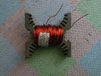
Yes, they're magnetic. They're coated with automotive primer. My main question is if I didn't cut them would they be more effective? I'm wondering if that's how the EI-core has good permability; because current can go all the way around and through the copper windings. I guess this material just sux, but I don't know why
Jimmy,
I think the time has come for you to cut your losses swallow a little pride and go with professionally mfg. inductors. Even with the best coil winding and test equipment, getting it right is difficult. When using a laminated core, unless you find a way to cement everything together like a solid rock, it will sing out at certain frequencies louder than your speakers. And that sound will pass thru the cone directly into your sweet spot.
If cost is still a problem, sell the copper you bought on this forum and use the cash to buy the coils you need.
Good luck
Chuck
Chuck Richey said:Jimmy,
I think the time has come for you to cut your losses swallow a little pride and go with professionally mfg. inductors.
Chuck
Never
I still got I couple tricks up my sleeve.
Seriously, I think you're right I will buy these http://home.hetnet.nl/~geenius/sales.html and unwind them to 12 mH. Right after my next couple of ideas fail.

I used the copper wire I bought from an electrical shop in my area to wind 10 smaller air core inductors and a 9 lb - 12 mH air core inductor; the 12mH I will not use.
Jimmy,
Is there any reason you just don't buy a pair of Perfect Lay 14Awg
Inductors from PE? I mean we're talking like less than $7.00 each
here.
I can understand wanting to DIY things, but unless you have an
inductor winder and an L/C/R bridge I would leave the winding to
the pro's.
Is there any reason you just don't buy a pair of Perfect Lay 14Awg
Inductors from PE? I mean we're talking like less than $7.00 each
here.
I can understand wanting to DIY things, but unless you have an
inductor winder and an L/C/R bridge I would leave the winding to
the pro's.
Winding inductors is easy. Just not for me right now because I'm having problems obtaining the cores I want at the price I want. If the inductors I wanted were $14 for both of them I would already have them.
I can get the cores I need for $50 a pair. I could probably get them for $50-60 laminated I figure. I have more time then money at the moment. I went through this same thing when trying to obtain 30 lbs of 12 gauge magnet wire. Now it's no problem.
The phrase "leave it to the pros" could apply to anything, including speaker buildng.
Anyway, I think I found some toroid cores that I will use for my x-over. They're on my other post in this from "Can you use a toroid for a speaker x-over?"
- Status
- This old topic is closed. If you want to reopen this topic, contact a moderator using the "Report Post" button.
- Home
- Loudspeakers
- Multi-Way
- How to measure inductance?