16-April-2022: After many inquires i have pulled the most important posts that describe the EnABL process to encourage people to pick up the technique
Tutourial #1 -- Materials
3 posts by Bud copied from the Hawthorne forum:
Materials:
The block paint I use comes from Polly S corporation, a division of Floquil / Testors. Any of their flat paints will do. But, if you do not want to stare at this lacy pattern every time you listen to music, use the flat clear paint. This is a bit more difficult to use, and I will cover what and why a bit later. Quite a wide variety of substitute materials have been tried successfully, by other people.
Next is Micro Scale micro gloss coating. Please do not substitute other materials for this one.
Both of these materials should be available from a decent hobby shop that sells primarily plastic models and trains. Both are also available on line, but there are box lot's you must buy. You will use it all, since EnABLing appears to be addictive, but it can look like a lot to purchase initially.
Next are speedball lettering pens. A-1 through A-5 in size and style. These will be in an art supply store, office product store or on line. You will also need a tip holder or two.
A useful addition to the arsenal are Rapidiograph technical pens. They make placing tiny dots on domes and whizzers much easier, for some and more difficult for others, like Dave from Planet 10, who uses them only under duress. Sizes from .02 through .085 are useful, but spendy.
Without the technical pens, and you can do without them with practice, you can expect to spend about $30 US.
Next go here and look over the pictures for the Fostex FE 127e. This is the stock EnABL configuration, for plain cone drivers, no whizzer. I will post the PDF data packet with conic sections and pattern rings in the next installment.
http://picasaweb.google.com/hpurvine/Fostex127ETreatment
Then here for a visual teaching aid, showing how to judge pen tip width Vs block pattern width, as the paint does spread a bit. Also shows how to use the pens for best flow and application control. Incidentally, you must burn the wax coating off of the tips before using them, or they will not work. If you roll the finger over the pics a little window of more or less pertinent commentary will pop up.
http://picasaweb.google.com/hpurvine/LowtherPreTreatment?authkey=VnmOeDveOOk
Look over the Fostex pics, note that you can combine the voice coil edge patterns for cone and dome into a three ring set, rather than four. Also note the weird dome center pattern. This, plus a drop of PVA on top of the center spot, controls dispersion for the entire driver and eliminates high frequency beaming.
PVA is poly vinyl acrylic, Parts Express sells it as surround to basket glue, Elmer's sells it as white wood glue and craft stores have it in their paper/scrap book sections. That dot is applied with a round tooth pick, with the point cut back to the barrel body, so about an 0.050" diameter droplet will do.
Go looking for the paints locally and if you are not finding them we can likely set up a group buy for a supplies packet, though I am not keen on being the distribution point.
The real thing to notice here is that the applied pattern, though neatly done, is not comprised of uniform sized, hard edged blocks, as the computer generated patterns would lead you to believe are needed. The inner rings are just sort of round blobs, with no attempt made to get them rectangular. This is another one of those very human endeavors, where close is good enough. So, download the hi rez photos and look at the application quality closely. You will get "good enough" pretty quickly.
Also there are a number of other driver types in this library and you are free to look at and download all of them.
http://picasaweb.google.com/home?tab=mq[/color]
Last edited:
Tutorial#2 -- Tools and their usage:
Pens
The calligraphy pen is a pretty specialized device. With almost 1000 years of development behind it, you can be sure it is made for it's job and designed to be used by humans. This means that even you can learn to use it.
There are a number of variables, pressure, speed of draw, angle of incidence and angle of accident.
The pressure controls the opening between the brass tip and the steel sub tip. this is a more sensitive relationship when the pen is used upside down and is a style A tip. When starting a pen stroke, push down slightly, before you move the tip. This wets the material uniformly across the tip of the pen's blade. If you push too hard you will loose the microsipe that holds the paint in suspension between the brass and steel tip portions, a blob will result. This can be quite useful, if you need to make a pattern block on a cone surface, under a whizzer cone, that blocks you from vertical access to where the pattern ring should be placed. At that point you choose tip width to suit the block length and rotate the pen 90 degrees with respect to the patterns linear direction around the cone circumference, making the block (or more likely, blob) without dragging the pen, just pushing down lightly, once.
The speed, in combination with the pressure, controls the flow of paint onto the surface. You will see this as the height of the paint bubble, trailing out behind the tip, before it sinks into the paper. If you move too slowly, with too much pressure, the paint will spread laterally from the pen stroke path. Getting both just right will provide a paint width about 5% wider than the pen tip width.
The angle of incidence is what angle the inverted tip has, with respect to the surface it is crossing. Look here to see the ideal angle.
http://picasaweb.google.com/hpurvin...photo?authkey=VnmOeDveOOk#5059385693917661122
This angle allows the most control of the opening between brass and steel tip, with the bearing surface confined to the steel blade and the brass not quite touching the surface. This angle provides an even, narrow pattern block.
The angle of accident is what happens to the pen stroke, if your elbow wrist and fingers are not ready to pull a pen stroke, without deviation from the shallow arc you are making, on a curved surface. You will think you are ready to make that stroke, but the mechanics of your arm are not properly aligned and the pen will move at an angle from the desired direction. The absolute best mechanism to aid you here is a sling that allows your elbow to rest on the bottom of a long pendulum. This is physically uncomfortable, and messes with proper blood flow to your arm, so your fingers get cold. It also looks ridiculous, so I don't use it either.
Still, you need to be aware of the movement your arm is going to impart, to that delicately balanced pressure/speed calamity, flowing from the pen tip, onto the complex curve you are describing in space. You cannot rely upon the cone to guide you here, and this is why I keep saying practice on some cones you do not care about.
An obvious point to note here is that you rotate the driver and keep your arm in a stable relationship with the center of that rotation. Since your other hand is doing the rotation, the bottle of paint will be unsupported and a semi conscious dip of pen point in paint, with a side tamp against the bottle neck to drain off excess material, can easily cause you to wear all the paint in the bottle. I will leave you to invent your own bottle control mechanism.
Patterns
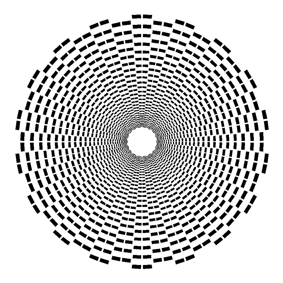
The basic design divides the circumference of the circle of interest into 36 10 degree segments. Alternating half of these, which then reside on a ,separate diameter circle, with a specific distance between the two diameter rings of blocks. Each 10 degree block is divided into two, 4 degree painted sections, with a two degree space between them. The alternating 10 degree sections do not have a space between their painted sections, in a circumferential sense. Instead, that space is provided by the radial distance between the rings and if you lined them all back up into one ring, these 4 degree sectors would butt up against each other, to make an 8 degree section.
Each painted block is 2 degrees in radial width, so the space between the painted blocks, in a set, is a square. Each ring is offset by two degrees in a radial distance and the edge of the outer block ring should be two degrees of radial distance from the edge that defines the surface you are controlling. So, a two ring pattern uses up 6 degrees of radial width, in a band around the circumference of the circle. And, it is two degrees of radial distance from the edge of that band to the edge of the circle. This is also true, with exceptions, of the inner edge of speaker cones, down by the voice coil. I will address those exceptions a bit further along.
All of this specificity is nice, but Murphy will show you just how useful it is, and pretty quickly too. I do have an EnABL lisp routine, written to run in Auto Cad 14, and maybe, possibly, in later versions. It also seems to be stable for use in 10 through 13. This is available for anyone who wants to use it to derive the conic sections I show, in most of the driver specific pattern formats. I generally import this DWG into Corel Draw because it takes the P line, with width, generated block from Auto Cad, and makes a rectangle out of it. You must then close the rectangle and fill it with black, or red or whatever suits your eye. Then you manipulate the multiple radial lines Corel also imports, on to another layer and do the same for the circumferential lines that describe the boundaries.
I can supply all of these related documents as a data packet for anyone who wants to dig into this portion and attain mastery over the EnABL process. You do not have to. Using a generic ring that you shrink or expand, just to give you a pattern guide, close to where you will put the blocks by eye estimation, is entirely suitable.
To adapt this pattern to cones with center domes, where you would theoretically want to place two rings of blocks on both cone and dome surface down near the voice coil, you can combine them into three rings. This flies in the face of that two degree spacing I was pointing to earlier.... so? Still works, and of course, actually works better than four rings. Look here to see what I mean.
http://picasaweb.google.com/hpurvine/Fostex127ETreatment/photo#5071580634373822754
Notice also that these are sort of round blobs, not rectangles, doesn't matter.
It is the interruption of the laminar portion of the boundary layer, with a pattern of obstacles rooted in that laminar portion, that performs the destruction of standing waves and the increase in height of the non laminar portion of the boundary layer, by forcing the joint between transverse wave, and resulting compression wave to be distributed in a vertically thicker volume, above the cone surface. This is the mechanism behind the greater amount of intelligible information EnaBL provides and the clarity and precision of transient leading and trailing edges.
To apply all of this to a large area , like a baffle, just take the entire peripheral length of the baffle and divide it into, 36 sections. Then divide those 10 degree lengths into a 4, 2, 4 relationship and you automatically have the more or less correct individual block length and width. Not that these block sizes make any sense in reality. But at least you have a starting point for changing things around to suit your self. Approaching corners can be theoretically tricky, but, just blunder through, making some blocks too long, some too short, or non existent, or even angled across the corner in frustration. Will not alter the effectiveness, at all.
I hope you get the impression that this is a pretty loose tool. You really can fool around with how it is applied and with what degree of accuracy, and still get the same audible benefits. However, too few blocks, below 30 sets of them, or too many, above 44 sets will affect the phase response of high frequencies, with respect to a 1 kHz nominal. Too few lags and too many advances this phase relationship, without materially affecting frequency response. So, if you have sharp peaks in high frequency information, you can aggravate their irritation, of your threat assessment correlator.
Bud
Pens
The calligraphy pen is a pretty specialized device. With almost 1000 years of development behind it, you can be sure it is made for it's job and designed to be used by humans. This means that even you can learn to use it.
There are a number of variables, pressure, speed of draw, angle of incidence and angle of accident.
The pressure controls the opening between the brass tip and the steel sub tip. this is a more sensitive relationship when the pen is used upside down and is a style A tip. When starting a pen stroke, push down slightly, before you move the tip. This wets the material uniformly across the tip of the pen's blade. If you push too hard you will loose the microsipe that holds the paint in suspension between the brass and steel tip portions, a blob will result. This can be quite useful, if you need to make a pattern block on a cone surface, under a whizzer cone, that blocks you from vertical access to where the pattern ring should be placed. At that point you choose tip width to suit the block length and rotate the pen 90 degrees with respect to the patterns linear direction around the cone circumference, making the block (or more likely, blob) without dragging the pen, just pushing down lightly, once.
The speed, in combination with the pressure, controls the flow of paint onto the surface. You will see this as the height of the paint bubble, trailing out behind the tip, before it sinks into the paper. If you move too slowly, with too much pressure, the paint will spread laterally from the pen stroke path. Getting both just right will provide a paint width about 5% wider than the pen tip width.
The angle of incidence is what angle the inverted tip has, with respect to the surface it is crossing. Look here to see the ideal angle.
http://picasaweb.google.com/hpurvin...photo?authkey=VnmOeDveOOk#5059385693917661122
This angle allows the most control of the opening between brass and steel tip, with the bearing surface confined to the steel blade and the brass not quite touching the surface. This angle provides an even, narrow pattern block.
The angle of accident is what happens to the pen stroke, if your elbow wrist and fingers are not ready to pull a pen stroke, without deviation from the shallow arc you are making, on a curved surface. You will think you are ready to make that stroke, but the mechanics of your arm are not properly aligned and the pen will move at an angle from the desired direction. The absolute best mechanism to aid you here is a sling that allows your elbow to rest on the bottom of a long pendulum. This is physically uncomfortable, and messes with proper blood flow to your arm, so your fingers get cold. It also looks ridiculous, so I don't use it either.
Still, you need to be aware of the movement your arm is going to impart, to that delicately balanced pressure/speed calamity, flowing from the pen tip, onto the complex curve you are describing in space. You cannot rely upon the cone to guide you here, and this is why I keep saying practice on some cones you do not care about.
An obvious point to note here is that you rotate the driver and keep your arm in a stable relationship with the center of that rotation. Since your other hand is doing the rotation, the bottle of paint will be unsupported and a semi conscious dip of pen point in paint, with a side tamp against the bottle neck to drain off excess material, can easily cause you to wear all the paint in the bottle. I will leave you to invent your own bottle control mechanism.
Patterns
The basic design divides the circumference of the circle of interest into 36 10 degree segments. Alternating half of these, which then reside on a ,separate diameter circle, with a specific distance between the two diameter rings of blocks. Each 10 degree block is divided into two, 4 degree painted sections, with a two degree space between them. The alternating 10 degree sections do not have a space between their painted sections, in a circumferential sense. Instead, that space is provided by the radial distance between the rings and if you lined them all back up into one ring, these 4 degree sectors would butt up against each other, to make an 8 degree section.
Each painted block is 2 degrees in radial width, so the space between the painted blocks, in a set, is a square. Each ring is offset by two degrees in a radial distance and the edge of the outer block ring should be two degrees of radial distance from the edge that defines the surface you are controlling. So, a two ring pattern uses up 6 degrees of radial width, in a band around the circumference of the circle. And, it is two degrees of radial distance from the edge of that band to the edge of the circle. This is also true, with exceptions, of the inner edge of speaker cones, down by the voice coil. I will address those exceptions a bit further along.
All of this specificity is nice, but Murphy will show you just how useful it is, and pretty quickly too. I do have an EnABL lisp routine, written to run in Auto Cad 14, and maybe, possibly, in later versions. It also seems to be stable for use in 10 through 13. This is available for anyone who wants to use it to derive the conic sections I show, in most of the driver specific pattern formats. I generally import this DWG into Corel Draw because it takes the P line, with width, generated block from Auto Cad, and makes a rectangle out of it. You must then close the rectangle and fill it with black, or red or whatever suits your eye. Then you manipulate the multiple radial lines Corel also imports, on to another layer and do the same for the circumferential lines that describe the boundaries.
I can supply all of these related documents as a data packet for anyone who wants to dig into this portion and attain mastery over the EnABL process. You do not have to. Using a generic ring that you shrink or expand, just to give you a pattern guide, close to where you will put the blocks by eye estimation, is entirely suitable.
To adapt this pattern to cones with center domes, where you would theoretically want to place two rings of blocks on both cone and dome surface down near the voice coil, you can combine them into three rings. This flies in the face of that two degree spacing I was pointing to earlier.... so? Still works, and of course, actually works better than four rings. Look here to see what I mean.
http://picasaweb.google.com/hpurvine/Fostex127ETreatment/photo#5071580634373822754
Notice also that these are sort of round blobs, not rectangles, doesn't matter.
It is the interruption of the laminar portion of the boundary layer, with a pattern of obstacles rooted in that laminar portion, that performs the destruction of standing waves and the increase in height of the non laminar portion of the boundary layer, by forcing the joint between transverse wave, and resulting compression wave to be distributed in a vertically thicker volume, above the cone surface. This is the mechanism behind the greater amount of intelligible information EnaBL provides and the clarity and precision of transient leading and trailing edges.
To apply all of this to a large area , like a baffle, just take the entire peripheral length of the baffle and divide it into, 36 sections. Then divide those 10 degree lengths into a 4, 2, 4 relationship and you automatically have the more or less correct individual block length and width. Not that these block sizes make any sense in reality. But at least you have a starting point for changing things around to suit your self. Approaching corners can be theoretically tricky, but, just blunder through, making some blocks too long, some too short, or non existent, or even angled across the corner in frustration. Will not alter the effectiveness, at all.
I hope you get the impression that this is a pretty loose tool. You really can fool around with how it is applied and with what degree of accuracy, and still get the same audible benefits. However, too few blocks, below 30 sets of them, or too many, above 44 sets will affect the phase response of high frequencies, with respect to a 1 kHz nominal. Too few lags and too many advances this phase relationship, without materially affecting frequency response. So, if you have sharp peaks in high frequency information, you can aggravate their irritation, of your threat assessment correlator.
Bud
Tutorial#3 -- Conformal Coating
How to tell just how much gloss to put on a cone.
First, listen to the EnABL patterned drivers for at lest two days, as the paint out gasses and sets up. You will notice a clarification process going on. After a coupe of days begin to play increasingly complex music, until the cone seems to be suddenly "overcome" and a garbled signal is emitted.
To the detriment of your relationship with your significant other, you are going to have to listen to this particular passage a number of times. While torturing this other person, you want to be on the floor, right in front of the speaker, drifting one ear back and forth, about an inch from the driver. You are trying to discover the general location of the corruption.
Chances are it is going to be from the cone, with a hotter area of sound coming from the center dome.
The Gloss coat can be thought of as an impedance dropping device. You want to use it to match the impedance of the cone with that of the center dome. This is much easier than it sounds, but tedious.
Let us assume the cone has been found to be the culprit in this garbling experiment. You will need a 3/8" wide, flat form, sable haired "area coverage" water color brush and a bottle of the Micro Scale Gloss coat. You are also going to need another small resealable container, because you really do not want to use the gloss material full strength, until you are very well accustomed to this impedance matching process.
Pour a small amout, 1/2 oz or so. of gloss into the new bottle and add about that much or a bit less clear water. Do not shake this stuff, ever. It froths instantly and may take 48 hours to settle down again. A gentle swirling motion or a gentle stirring with a small stick is what works best.
Now, dip the entire brush length into the opaque liquid and bring it up to the container neck. You will notice a blue white colored liquid gathered at the bottom of the brush. Touch one flat side of the brush to the wall and notice how quickly the liquid runs out, until there is just a tiny hint of blue/ white left on the brush end. This is a single side tamp. Take this loaded brush and on an absorbent piece of paper, like newsprint, or construction paper, draw a brush stroke with the tamped side down on the paper, while applying just enough pressure on the brush to curve the bristles. The brush ought to be at about a 30 degree angle from horizontal during this stroke and may be easiest to control if you hold the quill like you would a soup ladle, with the quill resting on the skin web between thumb and fore finger.
Notice how long a stroke you can make. Then, re dip the brush and tamp both sides, called a double tamp. Draw another stroke. Then, when the liquid gets spotty in it's application, decrease the angle further and sort of scramble the brush in circular patterns, noticing how much re coverage you need, to get a fairly uniform wetting.
These are the three brush stroke activities you will need, to coat all of the drivers you will ever see.
Now, take the brush and dip it into the liquid, tamp one side, apply the end to the voice coil edge of the cone and draw it straight out to the outer edge, either of the cone or the joint with the surround, lift the brush. If you are smart you will have made this first stroke at a point on the cone that you can mark, in some semi permanent fashion, so you know when you have made a complete revolution in coverage. You will use one tamped brush load for every stroke. Some times you will have to fill in between strokes, since the radial stroke pattern does not cover a larger area as you head toward the outer edge. Don't be too picky here, just try for the most even costing you can manage, without rebrushing any more than you have to.
Put this driver in a ventilated area and let it dry for 24 hours.
Listen to the driver. Same music, same distance but now you are listening for evenness of high frequency dispersion. Not very good, but probably a little better than before and much of the garbling will be gone.
The next coating is going to be done in a circular fashion as opposed to the radial brush path you used previously. You will be covering 1/4 of the cone with each stroke and will be moving up the cone from the voice coil edge to the outer termination, a brush width for every stroke, until you have completed a quadrant. Use the single tamp brush load for these strokes and again do the best job you can to keep them equal in amount of material applied. You will notice that the liquid goes much further now. Keep dipping the brush for every stroke just to help keep the same amount of material applied for every stroke.
When done, take one more brush load and double tamp it. Then apply a scramble coat on the center dome, getting as even a wetting as possible. Small bubbles will likely show up here and you want to try to pick them back up. off of the surface, as much as seems reasonable. They will eventually pop on their own.
Allow to dry for 24 hours.
Listen again. Now you are listening only for how even an output you get as you move your ear back and forth across in front of the driver. If you have a hot spot of high frequencies from the center dome, you will need to apply a dot of PVA on the dome center spot. Use that tooth pick barrel here. Allow this to dry for 4 hours and listen again. If the sound is well balanced, apply a tiny amount of gloss over this droplet and onto the surrounding, local, pattern.
Let dry for the usual 24 hours.
Now listen again. Is the balance still even? If so, you are done. If not, and the dome seems to have developed a diffuse hot spot, or, when sitting back in a listening position, the sound field is not immense, you will need one more coat of gloss, on the cone only.
This is with a brush load, double tamped. You apply a scramble coat over one entire quadrant of the cone. You can overlap at the quadrant sector edges a little. Try for as even a coat as you can get.
Let dry for 24 hours.
Listen.
The sound should come from behind and above the drivers and should spread a good bit beyond the drivers. You should notice that nothing seems to actually come from the drivers. As you move your head around, the sound remains balanced, very sharply focused in space and should not get richer as you pass directly in front of the drivers. There should be no place that is not a sweet spot.
If you perform this ritual a few times, on a variety of stereo pairs of drivers, you will teach yourself all you need to know to successfully EnABL any driver. I will warn you, that the whizzer aided full range drivers are more complex and more demanding of careful application of Gloss, to balance out the various impedances. You can get a whizzer cone driver to exhibit no hot spots, shoutyness and a full 180 degree arc of full range sound. The EnaBL thread has a number of treatment posts from me on FR whizzer drivers, that use the above terminology to describe what I did to get the drivers to behave... in a gloriously musical fashion.
Bud
Here are some additional EnABL aids (and some fun). People ask for a template for a specific driver. I work with the driver and fit a generic family of templates to the driver.
Here are some circular patterns that can be scaled before printig to provide almost any size template (up to size of paper) for almost any driver. When working around a dustcap, an exact circle in the middle of an appropriate size can be used to create a self centreing template.
http://frugal-phile.com/boxlib/More-generic-EnABL-patterns.pdf
dave
Since there seem to be a number of people interested in Gen 2 EnABL here is the method for finding pattern application positions called "The Tap Test".
There are three "sectors " to a tap.
Initial strike. This is what most people hear as a tap. We are geared to pay attention to intial arrival of any sound. You can use this portion of the tap sound to locate Raleigh waves and that is all. As you tap in a radial line there will be a sector that responds noticeably more vigorous than adjacent areas. This is very likely to be a Raleigh wave, but you cannot be certain until the rest of the driver is under control. Usually you must apply a damping material, in a fairly narrow band, on the other side of the diaphragm right under this area.
Mid tone. This is useful for finding subduction zones, usually immediately adjacent to Raleigh wave zones. This zone sounds dead compared to zones before and after, no tone to speak of. A pattern set in the middle of this zone and one just as it begins are the solution. Typically one pattern set at the point where the tone goes dead is sufficient and all that will fit. In 10 inch and larger cone drivers you may end up with more patterns here.
Decay tone. Here is where you will find most of the places to apply patterns. In listening to the decay you will have to ignore the other components from this tap. As you listen to the tap decay, while taping radially along the surface, you will notice a narrow zone where the decay seems to loose direction and then change direction as you move back and forth across it. Once you can focus on just the decay portion of the tap this will become fairly obvious. A pattern set in the middle of the directionless portion will disperse this activity completely.
The end product you are looking to achieve is a smooth change in direction of decay tone. From straight out or even slightly toward the center of the voice coil, when taping next to it, to aimed off the cone, parallel to the cone angle, out at the outer edge of the diaphragm. Dome diaphragms are a bit different but you will still find the same directional switch as you tap up the side of the dome. Same rule applies for placement and the eventual decay pattern will shift from lateral at the beginning of the dome to straight out on axis at the tip. In all cases the surface of the driver will seem to be "faster" than another untreated driver of the same part number. The tap will be dispersed very quickly with no echoes.
This same method is used to find application zones for baffles and boxes.
Some pictures of EnABLed drivers i have done.
https://www.diyaudio.com/community/threads/its-not-easy-being-green-just-pictures.213294/
I will be as helpful as i can, the world needs more EnABLers. :^)
dave
https://www.diyaudio.com/community/threads/its-not-easy-being-green-just-pictures.213294/
I will be as helpful as i can, the world needs more EnABLers. :^)
dave
Last edited:
People have also asked for supplies. U have the first 2 below and I will no longer need what i have stocked up so that is all avaialble.
For EnABL: Acrylic model train paint, clear gloss. Calligraphy nibs A2, A3, A4, A5, & 56 (the last 3 most used)
For some of the other mods: ModPodge (for paper cones) ZIG 2-way glue
and a selection of small (art) paint brushes.
dave
For EnABL: Acrylic model train paint, clear gloss. Calligraphy nibs A2, A3, A4, A5, & 56 (the last 3 most used)
For some of the other mods: ModPodge (for paper cones) ZIG 2-way glue
and a selection of small (art) paint brushes.
dave

Wrong thread to ask that question: https://www.diyaudio.com/community/threads/enabl-technical-discussion.119677/
But here ar ethe only measurements that show differences, but are open to interpretation. Mouse over to compare.
http://www.planet10-hifi.com/bud/garyP-test/
http://www.planet10-hifi.com/bud/johnK-test/
http://www.planet10-hifi.com/bud/mige-test/IR/AC/
http://www.planet10-hifi.com/bud/mige-test/IR/AD/
http://www.planet10-hifi.com/bud/mige-test/IR/BC/
http://www.planet10-hifi.com/bud/mige-test/IR/BD/
http://www.planet10-hifi.com/bud/mige-test/spectro/AC/
http://www.planet10-hifi.com/bud/mige-test/spectro/AD/
http://www.planet10-hifi.com/bud/mige-test/spectro/BC/
http://www.planet10-hifi.com/bud/mige-test/spectro/BD/
http://www.planet10-hifi.com/bud/mige-test/waterfall/AB/
http://www.planet10-hifi.com/bud/mige-test/waterfall/AC/
http://www.planet10-hifi.com/bud/mige-test/waterfall/AD/
http://www.planet10-hifi.com/bud/mige-test/waterfall/BC/
http://www.planet10-hifi.com/bud/mige-test/waterfall/BD/
http://www.planet10-hifi.com/bud/mige-test/waterfall/CD/
http://www.planet10-hifi.com/bud/mige-test/wavelet/AC/
http://www.planet10-hifi.com/bud/mige-test/wavelet/AD/
http://www.planet10-hifi.com/bud/mige-test/wavelet/BC/
http://www.planet10-hifi.com/bud/mige-test/wavelet/BD/
dave
I'm terribly sorry to hear that... I will do my best to learn the technique myself then.Sorry. Optic Nerve damage during the surgery i had some 6 years ago made it to difficult to see the smaller spots.
But i am happy to help anyonr who wants to learn.
dave
Can you please confirm that this is the right Microgloss coating? I'm asking because the guide is very specific about it.
https://agtom.eu/lakiery-bezbarwne/...o-coat-gloss-lakier-bezbarwny-blyszczacy.html
Regarding acrylic paints, can I substitute some other brand, such as this?
https://agtom.eu/mrhobby-gunze-h/342508-mrhobby-color-h317-fs36231-gray.html
Thank Dave. Would you happen to have copies of the photos from the guide? Because the links appear to be dead.
I had a read through other threads and I noticed some drivers seemed to get additional treatments. For example a sort of triangle shape across the entire cone. Can you comment on this please? I'm guessing it's driver-specific, but how do I work out if the driver needs it?
And a completely unrelated question, if I may - can the back of the cone benefit from the treatment as well? The reason I'm asking is I have a set of peculiar speakers where one the drivers is firing into the chamber as well as to the rear.
Attachments
- Home
- More Vendors...
- Planet 10 hifi
- How to EnABL