Hi john65b,
My Magnepans are 1990 model MG2.6/R. I definitely think speakers define the ‘sound’ of a system more than any other component. I love my Mags, although my current home has absolutely awful acoustics, by far the worst place I have ever lived sound-wise.
Still, I can hear the differences when I change stuff like bias and caps and such.
One of the things I have done in the past to improve the sound of my Maggies was to set up a makeshift 'Live End/Dead End' room. I have been thinking of starting a thread on this because it is a simple, fun way to improve your stereo without disassembling or measuring anything")
I bet there are people here that would be blown away by the improvement in sound this acoustic setup can achieve.
----
I didn’t mean they actually ‘destroyed’ Four Lakes – you could still play Vball there someday – it’s just really, really ugly and plain now. I get too emotional in my writing sometimes.
They cut out all of the small trees, brush, undergrowth etc. and trapped/removed all of the raccoons and other critters.
It’s like every other place now.
Lots and lots and lots of mowed grass. That’s what is left of the beautiful forest and nature area that Four Lakes once was. Everything that made it unique and ‘cool’ is gone – but you can still get drunk there, yayyy (blah to that).
People around here have no taste, when you get too rich too easily you lose all sense of what is really important. This was a beautiful place to live, now it is not because of all the wealthy idiots who invaded and trashed it.
My Magnepans are 1990 model MG2.6/R. I definitely think speakers define the ‘sound’ of a system more than any other component. I love my Mags, although my current home has absolutely awful acoustics, by far the worst place I have ever lived sound-wise.
Still, I can hear the differences when I change stuff like bias and caps and such.
One of the things I have done in the past to improve the sound of my Maggies was to set up a makeshift 'Live End/Dead End' room. I have been thinking of starting a thread on this because it is a simple, fun way to improve your stereo without disassembling or measuring anything
I bet there are people here that would be blown away by the improvement in sound this acoustic setup can achieve.
----
I didn’t mean they actually ‘destroyed’ Four Lakes – you could still play Vball there someday – it’s just really, really ugly and plain now. I get too emotional in my writing sometimes.
They cut out all of the small trees, brush, undergrowth etc. and trapped/removed all of the raccoons and other critters.
It’s like every other place now.
Lots and lots and lots of mowed grass. That’s what is left of the beautiful forest and nature area that Four Lakes once was. Everything that made it unique and ‘cool’ is gone – but you can still get drunk there, yayyy (blah to that).
People around here have no taste, when you get too rich too easily you lose all sense of what is really important. This was a beautiful place to live, now it is not because of all the wealthy idiots who invaded and trashed it.
The maggies MG2.6R are the ones that have the ribbon tweets?
Let me know you maggie mod. These magnepans are so dependant on correct placement.
I have always wanted to hang mine from a vaulted ceiling at the correct sweetspot angles. Of course, I don't yet have vaulted ceilings, but someday...
Let me know you maggie mod. These magnepans are so dependant on correct placement.
I have always wanted to hang mine from a vaulted ceiling at the correct sweetspot angles. Of course, I don't yet have vaulted ceilings, but someday...
Live End / Dead End Room
Hi john,
Yes, my Magnepans do have the ribbon tweeters, just not the awesome 5 foot long ones found in the Tympani series. Mine are about 3 feet long.
I have heard other Magnepans, the ribbon makes all the difference! I need look no further for tweeter technology.
I doubt you need to hang the speakers from the ceiling, definitely give this a try -
Live End / Dead End Room
Ah yes, I had a lot of fun with this once, it made my system sound more 3 dimensional than any other placement setup I have had since. I truly believe this is worth its own thread, so I may repost this info....
To create a LE/DE room, you simply need to dampen the end of the room with your speakers, and 'liven' the end of the room behind you.
There are many ways that you can achieve this, and many variations in room size and shape, so I can only give rough guidelines.
The best way to explain how to set this up is with a visual aid, so I have created just that and attached it.
Understand that the parameters do not have to be exact, nor do the materials have to be exotic, you simply need to deaden the speaker end of the room and brighten the area behind you.
When I lived at home, I used unzipped sleeping bags hung on the walls to deaden my dead end and used a bookshelf on my rear wall. The whole floor of my then listening room was carpeted, thus, not ideal, but the sound was still noticeably improved. The '3D' quality was like nothing I have heard since....
In the original article that I read in 'Stereo Review' or 'Audio' magazine, I cannot remember which, the author constructed a beautiful hardwood 'diffraction panel' for his rear wall. He did this by basically constructing a large bookshelf and, instead of books, glued hundreds of pieces of different sized hardwood together to make a very uneven - and diffractive - surface.
This works for ANY speakers, not just Maggies, so give it a try you guys, I would love to hear some stories of this application (That's why I will probably give it its own thread eventually).
Attachments
Looks like you are absorbing all the dipole effect sound emanating from behind the speakers - aren't you tripping up the soundstage doing this?
I will have to give it a try.
I have seen some designs where they enclose the back end of the maggies with a rolled carpet the entire length of the speaker - looking down on the maggies, it looks like a "D".
Hmmm....
I will have to give it a try.
I have seen some designs where they enclose the back end of the maggies with a rolled carpet the entire length of the speaker - looking down on the maggies, it looks like a "D".
Hmmm....
you might want to try a "quick and dirty" oscillation detector using an LED. you want to take an LED, put a 100 ohm resistor in series with it, then put a 4.7nf cap in series with the 100 ohm resistor. the "unused" leg of the LED becomes ground (polarity of the LED doesn't matter). the open leg of the cap becomes the input. then put a 1k resistor from the junction of the cap and series resistor to ground. the circuit is connected across the speaker terminals. any oscillation above 1 volt and above 20khz should light the LED, especially if the oscillation is continuous.
LED's are such useful devices......
yes, MOSFETS love hot-rodded bias a lot more than BJT's do. just don't overdo it, or your transistors will get over-done. i have a BJT design i'm working on, and in it, the crossover notch disappears at about 70mA bias, so i'll have to make the heat sink a bit bigger.
To john65b:
That is what you would think (about the dipole effect) but in reality I think the bipolarity of the speakers is still part of the 'effect'.
This is not just me talking, there is genuine acoustic science behind this and a great original article. In the original article, it was suggested that the 'perfect' LEDE room would have in-wall or recessed speakers, and I believe there was some mention as to even treating part of the ceiling above the speakers.
When I set up my LEDE room, it was completely carpeted and I left the ceiling reflective.
You must not forget the value of the diffractive rear wall - this is what gives you that big, wide perfectly focused soundstage.
The original article was very descriptive, informative and well written with more of the acoustic science than I have presented here.
Anyone interested would do well to try to hunt down the original article.
All I know of the original article is this:
It appeared between 1984 and 1990
It was printed in either 'Stereo Review' 'Audio' or 'High Fidelity' magazine, I cannot remember which one, but it was one of these.
Good Luck, and please post back if anyone finds it
-----------------------------------------------------------------------
To Hotsauce:
Sounds cool and I could believe the 'more dynamic' part but I myself have never heard instruments placed so accurately in space as with the regular LEDE setup.
In one of my apartments, I could not have the full setup so I hung a decorative southwestern style blanket on the wall behind and in between the speakers, it dramatically improved the imaging.
To unclejed613:
Thank you! This is becoming a genuinely useful thread, and I think I may just do exactly what you are describing.
About Bias:
I have recently noticed that my original XL-280 with proper 300mA bias sounds quite a bit more clear and dimensional than my eBay XL-280 set at the same bias - so it is apparently other factors in the case of the eBay XL-280 so I am in no hurry to crank the bias...
Attachments
Hey Unclejed613
Thanks for the advice on the oscillation detector...
I am one of those poor slobs in this hobby without a scope (well I have one - bought it on ebay for $20 - 'nuf said)
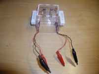
Very Cool! Pic attached with my 25W 8.2 load resistors - I just attach to the amp outputs and led light during oscillations. I built it in 25 minutes and will plan on using it on all my amps to spare possible damage to speakers... Invaluable to those that don't have a scope...I used sensitive ultra bright blue LEDs since the original red LEDs were difficult to see when lit.
Thanks again!
Thanks for the advice on the oscillation detector...
I am one of those poor slobs in this hobby without a scope (well I have one - bought it on ebay for $20 - 'nuf said)
Very Cool! Pic attached with my 25W 8.2 load resistors - I just attach to the amp outputs and led light during oscillations. I built it in 25 minutes and will plan on using it on all my amps to spare possible damage to speakers... Invaluable to those that don't have a scope...I used sensitive ultra bright blue LEDs since the original red LEDs were difficult to see when lit.
Thanks again!
Attachments
simple XL-280 stuff and a generic PS question
Posted these questions to diyaudio.com/Hafler dh-200/220 mods about 2 weeks ago w/no replies. Found this thread by accident.
1. Looking for power supply improvements or upgrade ideas other than those on TnT-audio.com or Elliot sound products
2. On the Hafler XL-280 schematic I noticed 2 types of grounds.
(Pg 17, below)
http://www.hafler.com/techsupport/pdf/XL-280_amp_man.pdf
One looks like a bent pitch fork (chassis ground?) The other, an inverted pyramid.
What concerns me is the 100nF caps that appear to rely on a chassis ground* connected to the final's PS rails near the MOSFETs.
* grounded through the heat sinks attached to case w/sheet metal screws.
Is it worth it to improve the ground? Relocate it to PS rail solder point & ground the other side? Can I run a connection to where C20 & C21 are grounded? Or where the RCAs have a way-better chassis ground?
3. I have an extra used set of PS caps from an XL-280. Are these a good choice to improve PS capacitance & ESR?
I'd like to squeeze these into one of my '280s. Is it worth the effort? The $ was right @ under $15 for 4 from ebay.
4. Also how to check DC offset? I did get a reply on bias/"idle" adjustment
5. DH-500 PS cap replacement: Nippon Chemi-Con or Mallory of about the same uF value?
Thanks tony
more XL-280 PS stuff
Another re-post from diyaudio.com/Hafler dh-200/220 mods w/no replies
I've heard from another hafler fan, the original "280" caps are superior to any other DH series PS caps
DH-200 model# & other info: 3186EE103U075BMA2; 362 8902 56699; 7800 micro F
XL-280 model# & other info: 3186DE782U075BJA2; 362 8710 56699; 10K micro F
both the same make, voltage, & temp specs.
What do you guys think?
thnx in advance, tony
one more XL-280 PS question for the day...
in simple terms, what does the diode between the front end supply voltage(FESV) and finals supply rails (FSR) do?
The FESV is higher @ 73V+ vs 63V+ for the FSR. If my knowledge of semi-conductors serves me, that diode prevents the FESV from returning thru the finals part of the PS. The FSR (lower) voltage can't over come the FE supply (higher) voltage.
So, again, why is it there?
thanks for being smarter than me, tony
Old thread and deviated somewhat from it's original topic, but...
You CANNOT go replacing caps without knowing what they do in the particular part of the circuit, and how a change of parameters will interact with it. Of course, it's not always possible in detail but certain things are well known.
For instance, do NOT change standard power rail caps to low ESR or increase the capacitance as the ESR interacts with charging current through various diodes and may poroduce all sorts of extra hash and garbage in the power lines which may, depending on circuits, contaminate the signal. They will also cause some regulator types to oscillate, sometimes well into the MHz range, the audible effects are sure to be there and they will be weird and not intuitive.
Do NOT put low SR parts where there is no DC bias, and I'm not talking mV here, but around 30-60% of nominal voltage written on the cap. Low ESR caps are not optimized for constant capacitance with AC voltage variations, rather for constant voltage with AC current variations. The ESR, though low, can be very non-linear. In other words, while low ESR may be applicable for various power supply rails, it is generally ntoa good idea in the 'signal path', and definitely not a good idea if there is very little DC bias on the cap.
Consider carefully replacing any type of cap you find in series with the signal (either input, output or feedback loop) with a different type. Also, any cap that defines the low end turnover frequency, such as bootstrap caps. These can have a big influence on the sound of the unit. This is not to discourage anyone from trying, but the changes need some knowledge and experience - NOT just internet reading on how what cap sounds as there are so many different places where it can be connected, and thus sound different - no capacitor has been made to suit every use, nor is a particular type just for one use, why else would there be different types in any manufacturer's lineup? If you want to hear how a 'neutral' electrolytic sounds, try replacing it with a foil cap, if it is practical. There are really only very few completely critical places where the capacitor type used is from a very small group or only one type. If you think you have identified one, try the foil cap trick. If it is not practical, bypass the existing one with a foil cap - this should be a small percentage of the original's capacitance, maximum 10%. This is NOT because you don't want to upset time constants - electrolytics are not too precise to begin with - but to prevent possible resonant peaks and dips with the ESL/ESR combinations of two caps in parallel. Use a good quality non-inductive foil cap, a metalized foil cap will do fine in most cases, as it's internal ESR is a bit higher and again less likely to form undamped C-ESL resonant circuits.
It is always a good idea to try and find the specs for the original caps and look for equivalents, which can generally be found with better success from the same manufacturer as the original ones.
Finally:
YES elecrolytics DO need a break-in period. The ones with low DC bias and AC current passing through in the low power sections of the amp, as well as the main filters where there are very high peak currents - especially if they spent some time on the shelf.
Beware of fake electrolytics! Yes, there are those around, purporting to have various well known brand names and types. i don't think I need to explain why you don't want them even near your equipment, let alone attempting to work within it.
I prefer to call "break in" of electrolytics as reforming the electrolytic to it's rated working voltage.
If I am truthful, I suppose my stance is that "break in" does not exist.
What is actually happening is that the electrolytics are reforming gradually to some lesser voltage while in circuit.
Reform all new, all old and all as new but old stock electrolytics using a low reforming current and gradually bring them up to full rated voltage and re-check leakage at this time and again after a further 1hour (or longer) of reforming.
If leakage appears to be continuing to lower then that confirms the capacitor is still in the process of reforming the insulation between the oppositely charged plates. Any caps that have excessive leakage should be reserved for the bin.
A further test after re-forming, but for which I have no experience, is to measure ESR and reject any that do not meet specification.
Fitting these reformed, low leakage caps, in spec ESR caps will result in an amplifier that does not need "breaking in". It simply needs to be warmed up to it's normal operating temperature.
Last edited:
I prefer to call "break in" of electrolytics as reforming the electrolytic to it's rated working voltage.
I would agree with 95% of what you wrote, and youa re right about the terminology.
However, some modern electrolytics are anything but simple and thus we can't always only speak of reforming. One point which you do bring up is operating temperature. I have found, precisely by using an ESR/D test after 'break in' - and I am going to explain why I am using the term here - that simply re-forming and actually having the cap in-circuit does make quite a bit of difference, most notably in the cases I outlined above. For instance, re-forming a large high ripple current cap put it's specs right on the mark but having it in circuit and re-testing later - the difference being several orders of magnitude of current passing through - showed better performance in the latter case.
In a complementary case, an audio cap was re-formed at 50% nominal voltage (17.5V), then under it's actual operating conditions, where the DC is closer to zero. In the latter case the amplifier stage in question showed almost the same distortion but a different harmonic profile, while testing the cap showed increased ESR for the latter case. I then tested resonance, the frequency ws virtually unchanged but the resonant peak was far lower, corresponding to the higher ESR.
These are not at all definite and universally conclusive tests, but they do show tht there is measurable difference in the performance of a cap depending on how it is used, and certainly IF it is used - therefore one can conclude that the real situation is only attainable once the cap has been place in the circuit it is intended for, and left operational for some time. Based on some experience with rebuilding vintage amps, where the sound is going to go after fresh caps are installed will be pretty much obvious in about 24 hours, this is where most of the change will happen (I have found only a few exceptions to that rule on both sides of the time scale), followed by the classic asymptote of things reaching homeostasis. After 3-7 days any change becomes practically imperceptible - but all this implies that sensible choice of cap vs role in the circuit have been made, and that they are all installed correctly.
I should also note that sometimes it's not at all easy discerning if the sound is better or worse, when it is different. As an example, a customer wanted a re-cap with as many small electros as is feasible, changed to foil caps. After he got the amp back he complained that there is a lack of 'sparkle' in the highs and at the same time everything is less smooth... I insisted he kept it running for a week and listening on occasion. His assessment changed once he was actually able to hear detail that he could not before - the reason, I would guess with some education, having to do with less distortion producing less harmonics which may add sparkle to some sounds but also smear details together resulting in the 'smoothing' effect. As always it's difficult to put objectivity to our subjective experience of that we listen to.
Last edited:
I still miss my 'sparkle'
Hello all, hello gp4jesus,
No, not much new Hafler news from my end these days, a snail ain't got nothin' on me when it comes to slow. In my defense, I had my fuel pump, timing belt, water pump, cam seal, PS pressure line, battery, and heater core all go out and need replacement on my car in the last 3 months!
Yes, I did all the work myself - DIYGeoStorm.
From what I have heard, the original XL-280 PS caps are excellent quality caps. I have two XL-280's and, therefore, two sets of caps - I know they are not all good so I plan to test them and select the best 4 of 8 for my 'reference' 280 with NEC FETS. The other XL-280 will eventually get 4 new (bigger) caps mounted to a Peter Daniels PS board instead of the original board as the original physical specs for the caps are near impossible to find.
My other planned experiment involves the 1000uF BiPolars on the circuit cards. I have acquired some Nichicon Muse (FZ? not sure...) BiPolars and will install under the appropriate blue moon.
Still miss my 'original' 280 sound... My advice - DO NOT touch the micas or the 1000uF BPs if you do not have to, these really affect the sound of the amp.
Cannot tell you the function of those diodes, just a tech type, but I have noticed their somewhat peculiar placement.
I will try to get stuff going this winter when I am cooped up, will post...
John
The ear can be deceiving when listening to sounds.
I hate a flat amplifier, love the distortion that valves bring.
You need to investigate the change in sound using equipment not your ears.
A white noise generator and a spectrum analyser is the way to go.
You can then see for certain what is really going on.
If you are looking to just like the sound then just change the capacitors to different makes until it sounds good to you.
I do not like panasonic fc also-they are lightweight, I think made to a price. Strange as it seems, I have used caps from discarded power supplys-sonically they appeal to me-usally 200 volt 220-330mfd. I have some pricey auricaps and some vitamin Q still not in use.Also I like Elna caps.
...and select the best 4 of 8 for my 'reference' 280 with NEC FETS.
what "Q" number on the PCB are these NEC FETs?
tony
I meant the input JFETs Q1-Q4. I have one amp with K163/J44 instead of the true 'superfets' (K147/J72) used on the earlier models. It sounds good.
The other amp I have has some oddball JFETs that I don't remember the number of. It is a later model than the former, both are Arizona models.
I was planning on replacing the JFETs in the 'lesser' amp with matched K170/J74's along with other mods.
The other amp I have has some oddball JFETs that I don't remember the number of. It is a later model than the former, both are Arizona models.
I was planning on replacing the JFETs in the 'lesser' amp with matched K170/J74's along with other mods.
Thanks for your detailed reply. Together with your earlier contribution, they bring balance to the discussion.I would agree with 95% of what you wrote, and you are right about the terminology.
However, some modern electrolytics are anything but ......................... As always it's difficult to put objectivity to our subjective experience of that we listen to.
- Status
- This old topic is closed. If you want to reopen this topic, contact a moderator using the "Report Post" button.
- Home
- Amplifiers
- Solid State
- How to destroy your high-end audio equipment...