Why I asked whether these were real measurements or simply from a simulation was because for the real build the actual construction and particularly the way the ground returns are implemented are crucially important to getting the best results.
The two stand out books have to Douglas Self's Audio Amplifier Power Design Handbook
Audio Power Amplifier Design: Amazon.co.uk: Douglas Self: 9780240526133: Books
And Bob Cordells Designing Audio Power Amplifiers
Designing Audio Power Amplifiers: Amazon.co.uk: Bob Cordell: 9780071640244: Books
Some useful info here:
Feedforward Class-B Amplifier.
Dear Wavebourn,
"Approach 2: separate SE amp plays class A role, but at some threshold additional devices get class C role to deliver higher current. No need for voltage bias. This approach was not understood and developed due to Peter Walker's patent with misleading description."
Please take your time and kindly post a workable design for us 'soldering technicians'.
--gannaji
Dear Wavebourn,
"Approach 2: separate SE amp plays class A role, but at some threshold additional devices get class C role to deliver higher current. No need for voltage bias. This approach was not understood and developed due to Peter Walker's patent with misleading description."
Please take your time and kindly post a workable design for us 'soldering technicians'.
--gannaji
For the beginning you can read a Quad 405 thread still active, even though the design is over-complicated. But it uses the same principle.
The better approach is covered
Where? What I saw, just musings around some particular topology from Peter Walker.
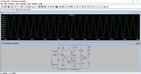
Here is an A+B example where I avoided shortcomings of voltage bias of output devices in class AB. Max current in class A is defined by R3 and R4, and depends on input signal. Transition to class B (not transition, but addition) is defined by R1 and R2 that again limit peak output current. The sound is, like in vacuum tube pentode amp with local feedback around output tubes.
Edit: however, current mirrors here are far from ideal, so adjustment of resistors depending on betas of output transistors are requires.
Edit: however, current mirrors here are far from ideal, so adjustment of resistors depending on betas of output transistors are requires.
Attachments
Last edited:
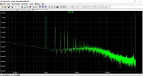
> Strangely enough there is a 2nd harmonic
I sure would expect a 2nd. Look at the current (and gain) in Q1 Q2 at mid-point, at pull-down, at pull-up. The Q1 Q2 current (and gain) increases when pulling-up the output.
Not as much as would be expected, because the Q2 load resistor is bootstrapped.
And the 4.7K does begin to swamp Q2 input needs. However hIE of Q1 is a non-negligible load on the NFB network.
So it's gonna have 2nd. How-much is a tough question. And there are *better* designs which leverage pennies of parts for hours of brain-pain.
High-level observations.
You have three stages of current gain. My impression is that four stages is more likely to lead to good input impedance (6K is on a low side) and solid output drive (what you want in a "power" amp).
Although bootstrapped, your output is really driven by 470r+570r divided by hFE of Q3Q4. 1,040 divided by say 100 is a 10 Ohm output, large signal; as high as your load. This is perhaps why you get 6Vpp when the plan should push 8Vpp. And while bootstrapping around one current-gain stage does help, bootstrap around two current-gain stages helps a lot more. Look at many 1970 amplifiers. Your 470r+570r may be 2K+2K, but Darlington output stage with hFE of 100*40= 4,000 makes large-signal output impedance near 1 Ohm, so you get more of your supply into your load.
This will be more important at the 20W level. The emitter follower Power Gain is just its current gain, hFE, maybe 100 but maybe 20. So a 20W output amp may need much of a Watt of drive signal to the final stage. A resistance-coupled amplifier (your Q2) has a maximum efficiency of 5.8%, and only under conditions that disagree with your power stage design. But taking 5%, a 1 Watt output driver has to be 20 Watts of dissipation, more than both your finals together. Higher hFE helps some, but cascaded hFE (hFE*hFE) helps a lot more.
- Status
- This old topic is closed. If you want to reopen this topic, contact a moderator using the "Report Post" button.
- Home
- Amplifiers
- Solid State
- How to control bias current in class AB output stage?