Hello all,
my question is about the EC900 tube that I use for my cdplayer is a grounded grid with anode choke, it works fine, but I wanted to know what is the calculation for the output impedance.
Before writing this post, I searched everywhere without finding the answer, could someone enlighten me?
Thank you
Stefano
Hello SY,
thank you for the answer, in fact, a very high output impedance.
Anyway, I think if I do not care about the choke (270 Hy, rs 2370 ohms, Z @ 1kHz 1.69Mohm ), I do not know the output impedance of the dac (tda1543a, yes, I still use the dac to granddad), it is directly connected to the cathode (rk 130ohm).
It's full of flaws, because I do not have the 2 volt described by Thorsten Loech but 1.7 volts is a bit noisy at low levels.
Why voltage of dac (about 0.82volt) do not add to the voltage of the cathode (about 1.3volt) to give 2.1 volts?,
instead, I have 1.7 volts.
Regards
stefano
Why voltage of dac (about 0.82volt) do not add to the voltage of the cathode (about 1.3volt) to give 2.1 volts?,
instead, I have 1.7 volts.
Regards
stefano
The input impedance of a grounded grid is very low. The voltage doesn't add directly probably due to voltage division between the Zo of the DAC and the Zi of the GG stage.
Hello everyone,
Here, I made a little diagram of what tubeplayer.
At the same time, I redid some changes in resistance (the first of the PSU and the cathode resistors), and I can actually get 2 volts, but at the expense of bias, which descends from 10.4 mA to 6 mA.
I'm not an expert, but the fact of sending the voltage of dac in the cathode, the load lines of the datasheet have nothing to do.
The tube is beyond the specs, the datasheet says maximum 200 volts, but that is one year and a half that it works like that with no problem.
Despite the small size, it is a strong tube, to my ears, the sound is really great, before I was operated with a ECC85 and even before with 6n1p, but the EC900 is more musical.
I want to change the transformer by another, with a secondary of about 170 volts ac instead of 280 volts, it would allow me to remove all the strength, I would build a secondary adjustable, it will be easier, I spotted some drawings.
The advice are welcome.
Regards
Stefano
Attachments
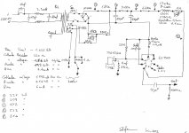
Pin 6 should be grounded, not left floating.
The resistors used for passive I/V on a 1543 need to be carefully calculated, and depend on supply voltage. In your case, the current through the valve complicates the calculation.
The resistance of 220 to ground plus the non-linear input impedance of the valve means that you are likely to get a little second-order distortion. This may be what you hear as "musical".
Pin 6 should be grounded, not left floating.
The resistors used for passive I/V on a 1543 need to be carefully calculated, and depend on supply voltage. In your case, the current through the valve complicates the calculation.
The resistance of 220 to ground plus the non-linear input impedance of the valve means that you are likely to get a little second-order distortion. This may be what you hear as "musical".
Hello,
there is no resistance to the I / V conversion, the output of dac go directly to the cathode, there is Vref and the cathode resistance, for the famous 2 volt.
The 100 nF on pin 6,
it is the inner shield tube, often I saw him put a capacitor there, he stayed because I did not hear any difference.
Stefano
Hello,
there is no resistance to the I / V conversion
Your schematic disagrees. As I said earlier, it's the 220R in parallel with the "looking in" impedance of the cathode (because of the plate choke, that ends up being rather high). This is not conducive to low distortion performance.
.
Hello,
You're absolutely right, I had forgotten the formula, which have given, because I do not have your value impedance dac.
Your schematic disagrees. As I said earlier, it's the 220R in parallel with the "looking in" impedance of the cathode (because of the plate choke, that ends up being rather high). This is not conducive to low distortion performance.
Hello,
You're absolutely right, I had forgotten the formula, which have given, because I do not have your value impedance dac.
Leaving the shield floating means that it can adopt whatever voltage it wishes, so the valve will not work as the makers intended. Note that this is not a shield around the valve innards, but between the grid and anode so more like the beam plates of a beam tetrode.
Hello,
Ok, I'll do as you say, I'll give it to the analog ground.
Is there a good solution to replace the resistance of 220ohm?
Maybe a system à la Broskie (BC109 + a resistance of small values), because I tried a green led 3mm., It gives the correct value of 2.04 volts, but listening to what is worse the resistance, I also tried the batteries with different voltages, apparently with the grounded grid, it will not work, the sound is low, the anode voltage rises sharply, however, I use the batteries for anode follower, there it goes very well.
Maybe a system à la Broskie (BC109 + a resistance of small values), because I tried a green led 3mm., It gives the correct value of 2.04 volts, but listening to what is worse the resistance, I also tried the batteries with different voltages, apparently with the grounded grid, it will not work, the sound is low, the anode voltage rises sharply, however, I use the batteries for anode follower, there it goes very well.
The output impedance of the DAC chip will be much higher than 220R, so you can use 220R for Rk in the formula for plate/anode impedance.
LEDs and batteries won't work here because they short out the signal. You need high impedance, the opposite of what is usually needed for cathode bias. You could try an adjustable CCS. You are trying to balance two things: the bias/current characteristics of the valve (which will change with ageing) and the output voltage requirements of the DAC chip. A few years ago I thought of doing something similar, but I couldn't think of a good way of doing it. The snag is that the AC and DC requirements are opposite to each other.
LEDs and batteries won't work here because they short out the signal. You need high impedance, the opposite of what is usually needed for cathode bias. You could try an adjustable CCS. You are trying to balance two things: the bias/current characteristics of the valve (which will change with ageing) and the output voltage requirements of the DAC chip. A few years ago I thought of doing something similar, but I couldn't think of a good way of doing it. The snag is that the AC and DC requirements are opposite to each other.
Last edited:
I ran some simulations of a circuit similar to yours. Though it suggests that the cathode resistor should be 470 ohms instead of 220 ohms. I did that to make the Iout pin of the TDA1543 take a voltage around 2.5V, so its I bias and I DAC current sources would have plenty of head room from the power supply rails. Get too close to a rail and the current circuits may get unhappy. I used a 6HA5 as a sub for the EC900, as I don't have a model for it and substitution guides suggest it as a sub.
The jazzies on the tube plate waveform are an artifact of the simulator. You may want to change the plate resistor for less gain.
The jazzies on the tube plate waveform are an artifact of the simulator. You may want to change the plate resistor for less gain.
Attachments
Last edited:
I ran some simulations of a circuit similar to yours. Though it suggests that the cathode resistor should be 470 ohms instead of 220 ohms. I did that to make the Iout pin of the TDA1543 take a voltage around 2.5V, so its I bias and I DAC current sources would have plenty of head room from the power supply rails. Get too close to a rail and the current circuits may get unhappy. I used a 6HA5 as a sub for the EC900, as I don't have a model for it and substitution guides suggest it as a sub.
The jazzies on the tube plate waveform are an artifact of the simulator. You may want to change the plate resistor for less gain.
Hello wa2ise,
sorry for not answering before, but my internet key has passed away.
I took the opportunity to experiment with the resistance of 470ohms and 2.5Volt, simulation put into practice, I have to say it's going pretty well.
I thought that with the tube, since it has a relatively steep slope, he needed to charge much more mA.
Now with about 200volt and 2.5mA, the sound has never been so good.
Then I made a PSU, according to this scheme took audiyofan.org, I actually work with a variac, because I do not have the right processor, I put my choke and 1.9Kohm, total 5.6 kohm as in the datasheet, with these changes, it is another cdplayer.
I have other cdplayer and dac, but in 1543, although this is by far the most cheap of all, I really like to listen.
Thank you,
Best Regards
Stefano
Attachments
Question about Salas shunt
Hello all,
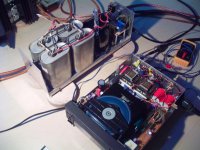
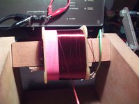
after advice SY, DF96, and Wa2ise I wound myself a transformer, because where I am, they work only in large batches, I had to do more than 200km., to build one, more, I have a lot of c-core, it was an opportunity to use them.
He goes about 255 volts dc @ 250mA.
I tried the regulator posted in my previous reply # 16, I just added a output capacitor (tested between 100nF and 1uF), otherwise it was a lot of noise, then DF96, offered me try a cCS on the cathode, this I am going after.
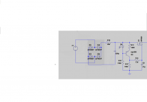
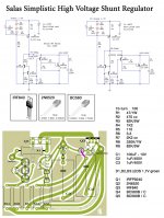
My question concerns a shunt SALAS, I do not know if it is still valid, but I made 250 volt version, we see in the diagram, because I had no sk 170 used in newer versions.
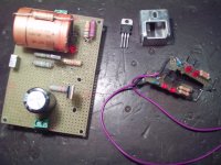
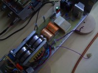
After assembly, I started, expected to stabilize a few seconds, then did a test with my finger on the transistors to see if everything was ok, that's where I I I'm pretty burnt on the IRF840, I say that with 3-3.6mA tubes that consume, it should not be a problem, that's why I installed the small radiator, that we see in the picture, so I switched off, I sawed in half, the radiator of a pentium, installed, nevertheless, still takes the IRF 104 ° celsius.
Is this normal, or there is a problem?
Thank you,
Regards
Stefano
Hello all,
after advice SY, DF96, and Wa2ise I wound myself a transformer, because where I am, they work only in large batches, I had to do more than 200km., to build one, more, I have a lot of c-core, it was an opportunity to use them.
He goes about 255 volts dc @ 250mA.
I tried the regulator posted in my previous reply # 16, I just added a output capacitor (tested between 100nF and 1uF), otherwise it was a lot of noise, then DF96, offered me try a cCS on the cathode, this I am going after.
My question concerns a shunt SALAS, I do not know if it is still valid, but I made 250 volt version, we see in the diagram, because I had no sk 170 used in newer versions.
After assembly, I started, expected to stabilize a few seconds, then did a test with my finger on the transistors to see if everything was ok, that's where I I I'm pretty burnt on the IRF840, I say that with 3-3.6mA tubes that consume, it should not be a problem, that's why I installed the small radiator, that we see in the picture, so I switched off, I sawed in half, the radiator of a pentium, installed, nevertheless, still takes the IRF 104 ° celsius.
Is this normal, or there is a problem?
Thank you,
Regards
Stefano
Attachments
Hello,
for ccs, I supplied 12 volts, the transistors are BC547C, with a load resistance of 4330 ohm, 132 ohm resistor to the cathode and the anode @ 1.8 mA.
I just wanted to say that for me, the most palbable quality of the dac is the medium, with the CCS, this quality disappears, the overall dynamics is worse than with a single resistor.
A few years ago, I tried a clock, it was the same, the original quartz, with a few pF. Moreover, sounds much better, but this is only my opinion.
Regards
Stefano
It is very easy to set up a 1543 wrongly, so you get clipping on either or both peaks. You need to get both the current and voltage right. You have to be careful to get both the 1543 and the valve happy at the same bias point. As I said in an earlier post, I could not think of a good way to do it.
...so I switched off, I sawed in half, the radiator of a pentium, installed, nevertheless, still takes the IRF 104 ° celsius.
In the July 2013 QST magazine, pg 62, there's a short article on the proper use of heat sink compound, aka goosegrease. This stuff is pretty good at filling small voids, but people tend to use way too much. It conducts heat better than air in the voids, but not as good as metal heatsinks do. Too much and you end up impeding the flow of heat. He says to use just enough to wet the surfaces. Maybe you used too much.
I added to my web page Modifying CD player DAC circuits my simulation (near the bottom of my page) and a brief mention of your report that it worked well. Thanks.
- Status
- This old topic is closed. If you want to reopen this topic, contact a moderator using the "Report Post" button.
- Home
- Amplifiers
- Tubes / Valves
- How to calculate, the output impedance of a tube with grounded grid