Sure its calculable--But....
There's SO many variables that need to be taken into consideration--it wouldnt be an easy thing to do.
Best way is simple 'shove a cap in there and see....' job.
Sometimes a simple conjunctive-filter on primary will do away with the need for a feedback cap--which can cause HF stability issues in some cases
.
Summit along the lines of 4.7K-10K and 1000pF 1.5KV will do nicely....
--Experiment while running a 1K and 10K square-wave, at about 1/4 to half of max power output across non-inductive load. check for ringing and overshoot. Trim resistor to minimise, but use as high a value as gets the job done--and no more.
To calculate the cap value you would need to determine the stray capacitance and Miller capacitance of each stage, then do a careful calculation or simulation of the loop frequency response in the ultrasonic region to determine the stability margin. Then choose a cap value which maximises this - an optimisation algorithm might help.
Or experiment, as everyone else does.
Or experiment, as everyone else does.
Calculation alone is very difficult. But you can make open-loop measurements, and work from there.
There's a description of how I did this for one particular amp here:
Push-pull driver board
Scroll halfway down the page to the section "Stability and global NFB".
Pete
There's a description of how I did this for one particular amp here:
Push-pull driver board
Scroll halfway down the page to the section "Stability and global NFB".
Pete
Calculation alone is very difficult. But you can make open-loop measurements, and work from there.
There's a description of how I did this for one particular amp here:
Push-pull driver board
Scroll halfway down the page to the section "Stability and global NFB".
Pete
If I apply this feedback with no compensation, I will still have 11dB of gain at 200kHz, where the phase crosses 180. What does that mean? That it will oscillate at 200kHz. And yes indeed, it does.
Did you have to feed 200kHz in to get this to oscillate or was it spontaneous resonant osc. from internal noise?
The small capacitor across the feedback resistor normally has a value between 50 – 500 pF.
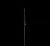
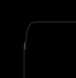
I use a simple and easy method to determine the needed value. I usually feed the amp with a 10 kHz square wave and connect a scope at the output of the amp. I also connect an 8-ohm resistive load. Now if the leading edge of the square wave has an overshoot, which is a sign of a small oscillation, I increase the value of the capacitor until the overshoot just disappears, and usually add little more than that. If you add too much capacitance, the square wave will round off too much. This method is working for me in most of the amps, and if it does not, the amp normally has problems that has that must be treated in other ways than just by the compensating capacitor in the feedback circuit.
I use a simple and easy method to determine the needed value. I usually feed the amp with a 10 kHz square wave and connect a scope at the output of the amp. I also connect an 8-ohm resistive load. Now if the leading edge of the square wave has an overshoot, which is a sign of a small oscillation, I increase the value of the capacitor until the overshoot just disappears, and usually add little more than that. If you add too much capacitance, the square wave will round off too much. This method is working for me in most of the amps, and if it does not, the amp normally has problems that has that must be treated in other ways than just by the compensating capacitor in the feedback circuit.
Attachments
Hi,
I am trying to calculate the optimal capacitor value in parallel to GNFB resistor. Is there an equation that I can use to do this?
Thanks
Better to adjust it empirically. Since this component is for extra phase margin at high frequencies, you'd need to know both the actual device internal capacitance and the circuit stray capacitance. Better to use a square wave -- carefully -- and add enough compensating capacitance to correct for ringing and/or overshoot
First check to make sure you actually need this for high frequency stability. I did two projects, and didn't need any extra capacitance, as the RF coax I used for connecting the gNFB added enough of its own capacitance to get the loop stable.
Did you have to feed 200kHz in to get this to oscillate or was it spontaneous resonant osc. from internal noise?
No signal needed, it started right up and oscillated...
Pete
By the way, after doing the open loop analysis, I did further testing with a square wave. That is probably the best way to tweak to a more ideal solution.
I actually don't remember if I wound up changing the cap, or not, in this case. But I usually do optimize as described by Miles and toriversen above.
Pete
I actually don't remember if I wound up changing the cap, or not, in this case. But I usually do optimize as described by Miles and toriversen above.
Pete
I don't have such HF intrumentations, just the PC sound card.
Ufortunately LTspice will not help me in the simulation (shows -150° at unity gain at 90Khz open loop, but if I rise too much the cap, the frequency response at 20k will drop too much..)
Without instrumentation what do you suggest: leave the cap out or just add an harmless 56pf Cap?
Ufortunately LTspice will not help me in the simulation (shows -150° at unity gain at 90Khz open loop, but if I rise too much the cap, the frequency response at 20k will drop too much..)
Without instrumentation what do you suggest: leave the cap out or just add an harmless 56pf Cap?
The minimum cap value is whatever stops your feedback loop from oscillating. The minimum value may be zero. Experiment may determine this.
The maximum cap value is whatever will not quite drop your HF rolloff too low. You should be able to calculate this.
Pick a value somewhere between the minimum and the maximum. That is about the best you can do with debugging without instrumentation.
The maximum cap value is whatever will not quite drop your HF rolloff too low. You should be able to calculate this.
Pick a value somewhere between the minimum and the maximum. That is about the best you can do with debugging without instrumentation.
- Status
- This old topic is closed. If you want to reopen this topic, contact a moderator using the "Report Post" button.
- Home
- Amplifiers
- Tubes / Valves
- How to calculate global NFB CAPACITOR. Is it needed?